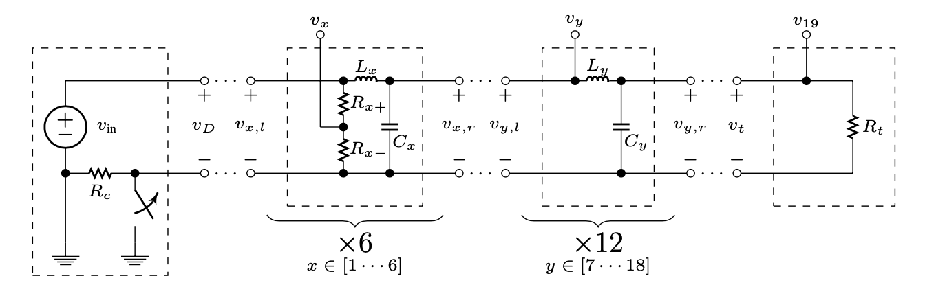
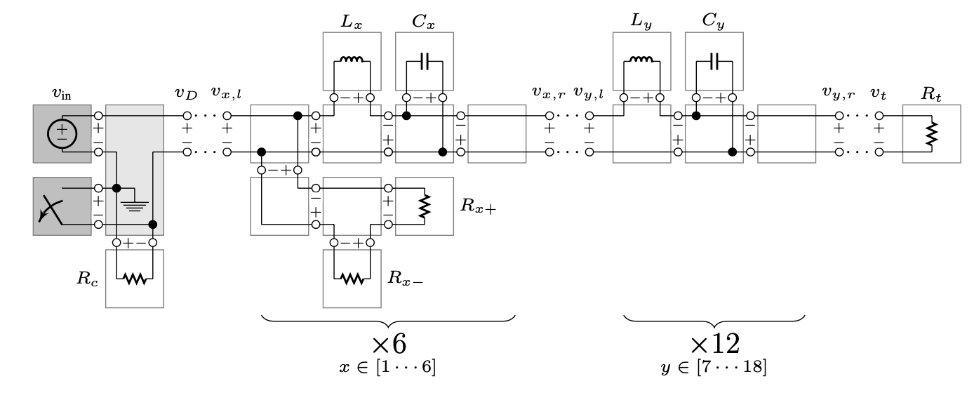
What’s the most efficient way to model this analog LC ladder? I know the values of all of the components. I’m also not really concerned about the first section of this schematic. There is a tap at each stage of the LC ladder that I need to access in a UGen graph function. I don’t always need all of them though. I only need 9 of them at a time and which ones I need/when is contextual. I’m also fairly certain the first 9 taps will have the same phase shift amount as the last 9, so I only need half of them.
.
So what I could do is, since there are a limited number of possible frequencies of sines into this circuit, make a bunch of signal/wavetable buffers. This seems inefficient.
I could also make a bunch of SinOscs with different phase offsets depending on the frequency. Each inductor is 0.5 H, so
(
{
var freq = 440;
var dry = SinOsc.ar(freq);
var prev;
var t = 9;
var taps = t.collect{ prev = SinOsc.ar(freq, p.(freq), t.reciprocal) };
SelectX.ar(LFTri.kr(6).unipolar * taps.size, taps) //modulate between different phase offset sines
}.play
)
This is, of course, not the same thing as modulating the phase argument of SinOsc. I don’t want interpolation, just crossfading different phase offset sine waves. This works, but it’s going to get heavy.
I could maybe also use Klang and supply phase offsets from the inductors? Or is there maybe a filter that will do this? I also thought of using Delay, but that doesn’t work because it doesn’t account for the input frequency and maybe that’ll also be heavy?