Has anyone managed to simulate these instabilities (with some dirty tricks, of course) using supercollider?
That analogue patch is simply genius. If it’s not out there, we should come up with something.

Has anyone managed to simulate these instabilities (with some dirty tricks, of course) using supercollider?
That analogue patch is simply genius. If it’s not out there, we should come up with something.
Indeed, BEA5 have been the ground were really amazing techniques have grown!
I’ve tried this one once, for me core of analog characteristic is the tape and a little bit of the mixer since the electronic modules used are pretty stable and does not have much difference from SC modules (this is obviously not true for devices like “stockhausen’s” Bruej & Kjaer filters or the noise generators). The Bruel & Kjaer filter used, since it is not moving, I think it would not make much of a difference from a digital one. As the reverb is also digital (PCM 90), the ones available at SC would be good to go as well.
I was trying to insert the tape simulation from Jatin Chowdhurry but I realized that they are still somehow unstable… at some point I got really strong glitches or blowups, some presets did not work… There is a port to scplugins, but I could not manage to handle it properly either…
For sure a little bit of distortion and noise spread over the digital flow would make it sound more analog like.
I’m sure it’s quite possible. The self-controlled feedback via amplitude de-modulator is the core, other things will influence the “flavor” of the system, of course. Sometimes one just need to inject something for it to work.
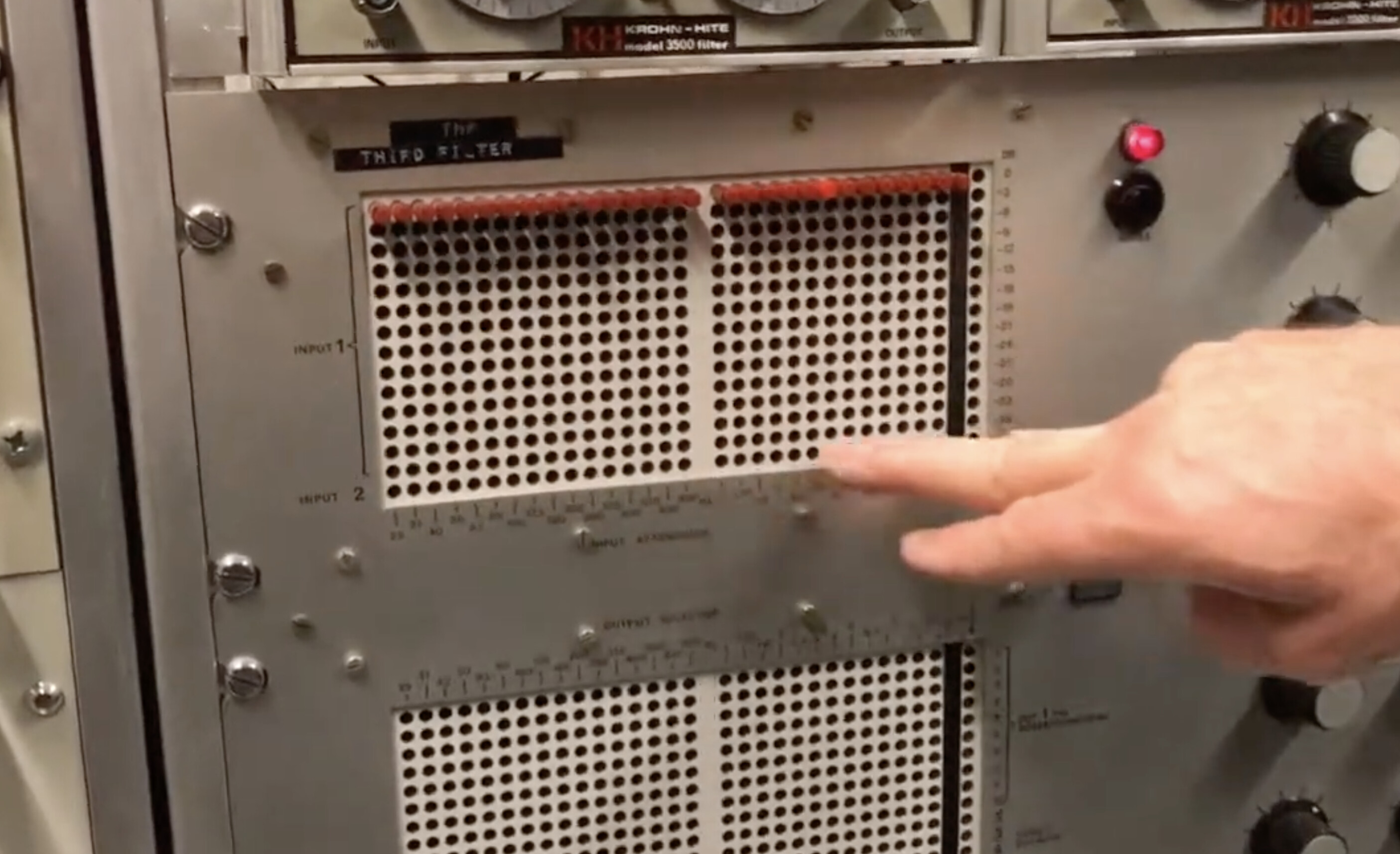
Does anyone know what the design of the third filter is? It looks like it might be similar to a Buchla 296 - basically a chain of mid-eq filters at predefined frequencies. Anyone know?
Sam
This one?
Almost sure that’s a self-build (BEA5/Sonology) matrix to control third-octave filter banks, output to 9 potenciometers.
I don’t know Buchla, but that model would be a vocoder? My guess is that they are related.
Another video on that channel is just about their filters, if you’re interested: https://www.youtube.com/watch?v=LsHLQihJq1U
It is not the same, but …
(
{
	var in, snd, ff, rmf, delayTime = 1.23;

	ff = MouseY.kr(50, 15000, \exponential);
	rmf = MouseX.kr(60, 6000, \exponential);

	in = LocalIn.ar(2) *15.dbamp;

	snd = DelayC.ar(DFM1.ar(in, ff, res: 0.91, noiselevel: 0.001), 1.0, delayTime);
	snd = snd * SinOsc.ar(rmf);

	snd = FreeVerb.ar(snd, 1, 0.9, 1);

	snd = Compander.ar(snd,snd,
		thresh: 0.1,
        slopeBelow: 1,
        slopeAbove: 0.1,
        clampTime:  0.01,
        relaxTime:  0.02);

	LocalOut.ar(snd);

	snd;

}.play;
)
Fun… here’s a slight variation which I kind of like:
(
{
	var in, snd, ff, rmf, delayTime = 1.23;
	ff = 1000;
	rmf = 10;
	in = LocalIn.ar(2)*0.5.dbamp;
	snd = DelayC.ar(
		DFM1.ar(in, ff, res: 0.91 + LFNoise1.ar(1).range(0.1.neg, 0.1), noiselevel: 0.001),
		2.0,
		delayTime + LFNoise1.ar(10).range(0.1.neg, 0.1));
	snd = snd * SinOsc.ar(rmf);
	snd = FreeVerb.ar(snd, 1.0, 0.9, 1);
	snd = Compander.ar(snd,snd,
		thresh: 0.1,
        slopeBelow: 1,
        slopeAbove: 0.1,
        clampTime:  0.01,
        relaxTime:  0.02);
	LocalOut.ar(snd);
	snd;
}.play;
)
(Edit: replacing SinOsc with LFSaw in the multiplication sounds nice too)
Does anyone know what the design of the third filter is? It looks like it might be similar to a Buchla 296 - basically a chain of mid-eq filters at predefined frequencies. Anyone know?
The BEA 5 manual is here: https://sonology.org/wp-content/uploads/2020/01/STUDIO-MANUAL-BEA-5-2005-opt.pdf
In it, it is written:
The THIRD-OCTAVE BAND FILTER (Bruel&Kjaer) consists of 29
parallel filters. The inputs to these filters are chosen by means of an
input-matrix, the outputs of the filters flow via a “programmable”
output-matrix. A circuit of 1O potentiometers offers the possibility of
mixing 1O arbitrarily chosen spectra with each other. This mixture is
available on output one. The outputs two to six are direct outputs, to
which filters can be assigned on the output-matrix. (For more elaborate
information, read the chapter “THIRD FILTER” in the old studio-manual).
Alas, I haven’t found the old studio manual. However, based on this (B&K Vocoder – Technology for Art and Education), it seems like that the B&K is model 1615. A manual for that is here: https://www.peel.dk/Bruel&Kjaer/pdf_manuals/1615,1614%20Octave%20and%201-3%20Octave%20Filter%20Sets%20(Instructions%20manual).pdf
The 1615 manual describes the filters as 6-pole Butterworth bandpass filters, with schematics included. Also included are the center frequencies and bandwidths.
The following frequencies of the spectrum are used:63Hz, 80Hz, 100Hz, 125Hz, 160Hz, 200Hz, 250Hz, 315Hz, 400Hz, 500Hz, 630Hz, 800Hz, 1000Hz, 1250Hz, 1600Hz, 2000Hz, 2500Hz, 3150Hz, 4000Hz, 5000Hz, 6300Hz, 8000Hz, 10kHz, 12.5kHz.
Does it say more about bandwidths etc?
Yep, exact frequencies and bandwidths for all bands in the 1615 are given in the 1615 manual: https://www.peel.dk/Bruel&Kjaer/pdf_manuals/1615,1614%20Octave%20and%201-3%20Octave%20Filter%20Sets%20(Instructions%20manual).pdf
And those toys are OSC-controlled? We can have a real party there.
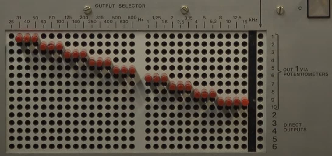
Here are the center frequencies and bandwidths of the BEA5 third-octave filter.
Note the center frequencies on the matrix panel match those listed in the 1615 manual.
Also note that the video shows the matrix pins grouping the third-octave bands into groups of three, therefore an octave, with the exception of the highest frequencies, grouped into four, and the lowest band (25 Hz), which is not in the output.
| Center Frequency (Hz) | Bandwidth (Hz) |
|---|---|
| 25 | 5.8 |
| 31.5 | 7.3 |
| 40 | 9.2 |
| 50 | 11.6 |
| 63 | 14.5 |
| 80 | 18.3 |
| 100 | 23 |
| 125 | 29 |
| 160 | 37 |
| 200 | 46 |
| 250 | 58 |
| 315 | 73 |
| 400 | 92 |
| 500 | 116 |
| 630 | 145 |
| 800 | 183 |
| 1000 | 230 |
| 1250 | 290 |
| 1600 | 370 |
| 2000 | 460 |
| 2500 | 580 |
| 3150 | 730 |
| 4000 | 920 |
| 5000 | 1160 |
| 6300 | 1450 |
| 8000 | 1830 |
| 10000 | 2300 |
| 12500 | 2900 |
| 16000 | 3700 |