Noob: How to do classic (DX7 style) operator feedback?

Hi, I am currently trying to learn how to do FM (DX7 style) in SC. The DX7 allowed phase modulation feedback not only inside a single operator (as in algorithm 3 and 5), but also over several operators (as in algorithm 4 and 6):
DX7_algos3456

I learned that SinOscFB has a built-in phase modulation feedback, which gives the acoustic result I am looking for, but only for one oscillator.

I would like to learn how a phase modulation feedback loop over several operators can be achieved. As first step, I tried to rebuilt the phase modulation feedback of SinOscFB using the standard SinOsc like this:

(
SynthDef(\PM, {
	arg index=3, freq=200;
	var sig=0;
	sig = SinOsc.ar(freq: freq, phase: index*sig);
	Out.ar(0, sig*0.1);
}).play
)

Didn’t work. But why? Why is SinOsc unable to use its own output?
Then I tried this…

(
SynthDef(\PM, {
	arg index=3, freq=200;
	var sig=0;
	sig = SinOsc.ar(freq: freq);
	sig = SinOsc.ar(freq: freq, phase: index*sig);
	Out.ar(0, sig*0.1);
}).play
)

…which only increased the amount of phase modulation, but did not give the feedback result of using SinOscFB:

(
SynthDef(\PM, {
	arg index=3, freq=200;
	var sig=0;
	sig = SinOscFB.ar(freq: freq, feedback: index);
	Out.ar(0, sig*0.1);
}).play
)

My hope is: If I understand how phase modulation feedback inside SinOscFB, I can create phase modulation feedback over an arbitrary number of SinOsc's.

I searched for “Feedback FM”, as well as “Feedback Operator” in this forum, as well as for “Feedback” in SC-IDE’s documentation, but the results were not helpful for me.

Please, how can I make this happen? And how does SinOscFB achieve it? Thanks much in advance!

P.S. I am aware that this can be viewed as a somewhat futile exercise, as there is the FM7 UGen emulating an NI FM7 which can emulate a DX7 and much more complex FM scenarios. But I would really like to learn how the feedback works. :slight_smile:

2 Likes

You can use LocalIn and LocalOut in your SynthDef to reinject the output of any SinOsc to the input of another SinOsc, but with a block size delay.
As far as I know, it’s difficult to do 1-sample feedback in SC, apart from setting the block size to 1 and reducing dramatically performance.

1 Like

check out @dkmayer miSCellaneous_lib which has a facility for single sample feedback

1 Like

there is a great video about pm cascades including feedback by @alikthename 7: FM[2] - Frequency or phase? - Musical Sound Design In Supercollider - YouTube

2 Likes

@Geoffroy: Thank you, this did the trick!

(
SynthDef(\PM, {
	arg index=2, freq=200;
	var sig;
	sig = SinOsc.ar(freq: freq, phase: index*LocalIn.ar(numChannels: 1, default: 1));
	LocalOut.ar(sig);
	Out.ar(0, sig*0.1);
}).play
)

I am assuming that the audible difference between the LocalIn/Out and the SinOscFB version are due to block size delay with LocalIn/Out, whereas SinOscFB might use 1-sample feedback, no?

@semiquaver: Thank you for the pointing me to @dkmayer’s SC extensions. I will read about installing extensions (I have no idea about this currently), and then check out the sonic difference between block size feedback and 1-sample feedback.

@dietcv: Thank you for the video by @alikthename, this was very helpful not only regarding LocalIn/Out usage, but also regarding the behavioral differences in different registers between PM and FM.

hey, im not sure if im right with the LocalIn placement but this seems to work:

(
SynthDef(\pm, {
	arg freq = 500, index=1, iScale=5, atk=0.01, rel=3, cAtk=4, cRel=(-4);
	var sig, car, mod, gainEnv, iEnv;
	
	iEnv = EnvGen.kr(
		Env(
			[index, index * iScale, index],
			[atk, rel],
			[cAtk, cRel]
		), doneAction: Done.none;
	);
	
	gainEnv = EnvGen.kr(
		Env.perc(atk, rel, curve: [cAtk, cRel]),
		doneAction: Done.freeSelf
	);
	
	mod = SinOsc.ar(freq * \mRatio.kr(1), mul: iEnv + LocalIn.ar(1));
	car = SinOsc.ar(freq * \cRatio.kr(1), mod.wrap(0, 4pi));
	
	LocalOut.ar(car * \fb.kr(0.1));
	
	sig = car * gainEnv;
	
	sig = Pan2.ar(sig, \pan.kr(0), \amp.kr(0.25));
	sig = LeakDC.ar(sig);
	Out.ar(\out.kr(0), sig);
}).add;
)

Synth(\pm, [\freq, 46.midicps, \atk, 0.01, \rel, 1, \fb, 0.1, \index, 10, \iScale, 1, \mRatio, 2, \cRatio, 1]);

Thank you for the example (which introduced me to LeakDC and reminded me I needed to learn about Named Controls :slight_smile: ).

It sounds nice, but I am not sure if the LocalIn placement is “correct” (in terms of mimic DX7-style operator feedback). From how I understand the code (as I am a noob, I may be wrong!), this line means you are using the LocalIn bus signal to modulate the mod’s amplitude:
mod = SinOsc.ar(freq * \mRatio.kr(1), mul: iEnv + LocalIn.ar(1));

But if the phase is to be modulated, it should read like this, no?
mod = SinOsc.ar(freq * \mRatio.kr(1), phase: LocalIn.ar(1), mul: iEnv);

The results are similar, but not identical. The AM version with \fb, 2 sounds somewhat similar to the PM version with \fb, 0.4: With these feedback values the AM version is brighter but more static than the PM version.

hey, the phase of the carrier should be modulated by the modulator.
thats the reason why mod is placed as a phase argument for the carrier signal and i think the feedback signal should be added to the modulating signal, but could be wrong. I think you are not modulating the phase of the phase here. maybe someone else knows :slight_smile:
mod.wrap(0, 4pi) limits the carrier signal to stay below the nyquist frequency of sampling rate (44.1 kHz) / 2 otherwise you induce aliasing artefacts for frequencies higher than 22.05 kHz when using higher modulation indices and carrier-to-modulator ratios.
when dealing with modulating synthesis i always add LeakDC or use a HPF.

I may be not understanding it, but if you want to add the feedback signal to the modulating signal, shouldn’t it read
mod = SinOsc.ar(freq * \mRatio.kr(1), mul: iEnv) + LocalIn.ar(1);
instead of the feedback signal modulating amplitude:
mod = SinOsc.ar(freq * \mRatio.kr(1), mul: iEnv + LocalIn.ar(1));

I guess it depends on the sonic goal one wants to achieve. I like the way “FM” sounds in the DX7, and in the DX the phases of operators are modulated, both in the standard modulator-carrier case and in the feedback case.

Also the SC documentation for SinOscFB points to this behavior:
“SinOscFB is a sine oscillator that has phase modulation feedback; its output plugs back into the phase input. Basically this allows a modulation between a sine wave and a sawtooth like wave. Overmodulation causes chaotic oscillation. It may be useful if you want to simulate feedback FM synths.”

This leads me to believe that the feedback signal should modulate the phase, even in the case of the feedback loop going around several operators:
mod = SinOsc.ar(freq * \mRatio.kr(1), phase: LocalIn.ar(1), mul: iEnv);

Thank you for the tip regarding limiting the carrier signal with .wrap!

i think in the case of SinOscFB you are routing the carrier signal back into its phase input for a self modulating feeback loop. There is not an additional modulating signal as a phase argument for the carrier signal.

in the case of pm with 1 carrier and 1 modulator we have two separate signals.
when you increase the amplitude of the modulating signal by increasing the modulational index you are increasing the phase modulation depth of the carrier signal up to the point where the phase of the carrier gets wrapped at 4pi.

a.) i think one question is when you have a cascade of several modulators/carriers do you plug them into each others phases or do you add or multiply the signals by each other.
In the discussion below the video ive posted one possible solution for a DX7 style cascade was this:

cascade_0 = SinOsc.ar(freq * \ratio3.kr(1)) * EnvGen.kr(Env.perc(att3, rel3), gate); 
cascade_0 = SinOsc.ar(freq * \ratio2.kr(1), cascade_0.range(0, mInd2))  * EnvGen.kr(Env.perc(att2, rel2), gate);
cascade_0 = SinOsc.ar(freq * \ratio1.kr(1), cascade_0.range(0, mInd1))  * EnvGen.kr(Env.perc(att1, rel1), gate);

b.) and the other question is how to deal with the mul argument when wanting to add the previous operator to the next operator’s modulator for a kind of SinOscFb self modulating thing.
i think you are right that mod and mod2 are not equivalent.

(
{
	arg freq=220, index=2;
	var mod, mod2, mod3, add;

	add = SinOsc.ar(freq);

	mod = SinOsc.ar(freq, mul: index)  + add;
	mod2 = SinOsc.ar(freq, mul: index + add);
	mod3 = SinOsc.ar(freq) * index + add;

	[mod, mod2, mod3];
}.plot;
)

probably the LocalIn should be placed like this:

(
SynthDef(\pm, {
	arg freq = 500, index=1, iScale=5, atk=0.01, rel=3, cAtk=4, cRel=(-4);
	var sig, car, mod, gainEnv, iEnv;
	
	iEnv = EnvGen.kr(
		Env(
			[index, index * iScale, index],
			[atk, rel],
			[cAtk, cRel]
		), doneAction: Done.none;
	);
	
	gainEnv = EnvGen.kr(
		Env.perc(atk, rel, curve: [cAtk, cRel]),
		doneAction: Done.freeSelf
	);
	
	mod = SinOsc.ar(freq * \mRatio.kr(1), mul: iEnv) + LocalIn.ar(1);
	car = SinOsc.ar(freq * \cRatio.kr(1), mod.wrap(0, 4pi));
	
	//LocalOut.ar(mod * \fb.kr(0.9));
	LocalOut.ar(car * \fb.kr(0.9));
	
	sig = car * gainEnv;
	
	sig = Pan2.ar(sig, \pan.kr(0), \amp.kr(0.25));
	sig = LeakDC.ar(sig);
	Out.ar(\out.kr(0), sig);
}).add;
)

Synth(\pm, [\freq, 46.midicps, \atk, 0.01, \rel, 1, \fb, 0.9, \index, 10, \iScale, 0.5, \mRatio, 2, \cRatio, 1]);

but overall im also not 100% sure about the things ive been saying maybe someone else can clarify.
thanks a lot :slight_smile:

This question has been raised in the video, and I wondered why it was actually raised, for several reasons. Please let me try to explain.

Effort
I think we agree that in case of a 2 operator stack, the modulator modulates the phase of the carrier like this:

	mod = SinOsc.ar(freq: car_freq * mod_ratio);
	car = SinOsc.ar(freq: car_freq, phase: mod_index * mod);

If this is correct, I doubt that Yamaha has implemented the 3 operator stack differently. Wouldn’t it be inefficient to implement different ways on how an operator interprets incoming phase data depending on whether or not a modulator is modulating a carrier or a modulator? Given the limited resources, I find this hard to imagine. But I am not an engineer, I may be wrong.

Sound
So instead of theoretical musings, I’ll try an audible example. This rendition of one of the DX7’s more popular sounds, Preset 26 “TUB BELLS”, is extremely poor, but hopefully good enough to do the trick:

(
SynthDef(\PM_2OP_Tubular, {
	arg car_freq=200, mod_ratio=3.5, mod_index=2;
	var env, car, mod;
	env = EnvGen.kr(envelope: Env.perc(releaseTime: 4), doneAction: 2);
	mod = SinOsc.ar(freq: car_freq * mod_ratio) * env;
	car = SinOsc.ar(freq: car_freq, phase: mod_index * mod) * env;
	Out.ar(0, car!2 * 0.2);
}).play
)

Now let’s put one operator below this 2 operator stack. To make this test more obvious, I’ll use the fixed frequency setting for this new operator. This DX7 feature allowed to decouple an operator’s frequency from the keyboard and set it to an arbitrary fixed frequency between 0.1 and 9772 Hz. With very slow frequencies it was used for chorus- or PWM-like effects. With the bells on top, it sounds like this:

(
SynthDef(\PM_3OP_Tubular, {
	arg car_freq=200, mod_ratio=3.5, mod_index=2;
	var env, new_car, car, mod;
	env = EnvGen.kr(envelope: Env.perc(releaseTime: 4), doneAction: 2);
	mod = SinOsc.ar(freq: car_freq * mod_ratio) * env;
	car = SinOsc.ar(freq: car_freq, phase: mod_index * mod) * env;
	new_car = SinOsc.ar(freq: 1, phase: car) * env;
	Out.ar(0, new_car!2 * 0.2);
}).play
)

Which is how it would have sounded on my old DX7 if I still had it.

Now let’s try the suggested alternatives, first the addition (as I understand it, please correct me if I am wrong):

(
SynthDef(\PM_3OP_Tubular_mix, {
	arg car_freq=200, mod_ratio=3.5, mod_index=2;
	var env, new_car, car, mod;
	env = EnvGen.kr(envelope: Env.perc(releaseTime: 4), doneAction: 2);
	mod = SinOsc.ar(freq: car_freq * mod_ratio) * env;
	car = SinOsc.ar(freq: car_freq) * env;
	new_car = SinOsc.ar(freq: 1, phase: car + mod) * env;
	Out.ar(0, new_car!2 * 0.2);
}).play
)

Which sounds one octave lower, also the harmonic structure is duller. So I doubt that this addition is the right way to mimic serial 3 operator stacks.

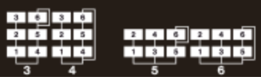
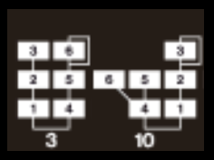
It is not a wrong way in itself though, as the DX7 offered dedicated algorithms to accomplish such parallel mixture, see e.g. operators 4,5 and 6 in algorithm 10:
DX7_algo3_10

Now on to the other suggested alternative, the multiplication (again, as I understand it, please correct me if I am wrong):

(
SynthDef(\PM_3OP_Tubular_mul, {
	arg car_freq=200, mod_ratio=3.5, mod_index=2;
	var env, new_car, car, mod;
	env = EnvGen.kr(envelope: Env.perc(releaseTime: 4), doneAction: 2);
	mod = SinOsc.ar(freq: car_freq * mod_ratio) * env;
	car = SinOsc.ar(freq: car_freq, mul: mod_index * mod) * env;
	new_car = SinOsc.ar(freq: 1, phase: car) * env;
	Out.ar(0, new_car!2 * 0.2);
}).play
)

Also a considerably different harmonic structure.

This is why I am convinced that phase input signals are handled equally in all operators, independent of their positions in the stack: Each one is modulating the phase of the one below it. Phase input signals are mixed/added in case operators are going in parallel into an operator below. But I think we can rule out multiplication. What do you think?

If they are a stack of operators:

3
|
2
|
1

Then 3 modulates 2’s phase, and 2 modulates 1’s phase.

If you have multiple modulators at the same level affecting the same carrier:

2   3
 \ /
  1

Then 2 and 3 are mixed. In digital audio, “mixed” means added, not multiplied.

Amplitude modulation (multiplying) before frequency/phase modulation might sound cool but it wouldn’t sound like DX.

hjh

5 Likes

Reopening this topic with a small question exactly on this regard, but to short for a new post:

When I set SinOscFB feedback argument to 0.0 is it still performing some kind of phase modulation ? Or maybe some residual calculation on the phase ?

These two examples should or should not perform the exact same thing? They do produce different sound results:


(
{
	var carfreq=200,modfreq=400*2.5,
	modindex=XLine.kr(0.01,3).poll;
	SinOscFB.ar(carfreq + (modindex*modfreq*SinOscFB.ar(modfreq,0.0)),0.0,0.125)
}.play
)

(
{
	var carfreq=200,modfreq=400*2.5,
	modindex=XLine.kr(0.01,3).poll;
	SinOsc.ar(carfreq + (modindex*modfreq*SinOsc.ar(modfreq)),0,0.125)
}.play
)

Using DC.ar(0.0) does not seems to help…

First, I am a noob at SC, so please take the following with a grain of salt.

After experimenting with your code I believe that SinOscFB reacts differently to extreme frequency modulation than SinOsc, which gives the audible sonic differences. So changing this…

(
{
	var carfreq=200,modfreq=400*2.5,
	modindex=XLine.kr(0.01,3).poll;
	SinOscFB.ar(carfreq + (modindex*modfreq*SinOscFB.ar(modfreq,0.0)),0.0,0.125)
}.play
)

…into this by replacing the SinOscFB carrier with a SinOsc removes the sonic difference:

(
{
	var carfreq=200,modfreq=400*2.5,
	modindex=XLine.kr(0.01,3).poll;
	SinOsc.ar(carfreq + (modindex*modfreq*SinOscFB.ar(modfreq,0.0)),0.0,0.125)
}.play
)

I am sorry that I can not offer a better explanation.

P.S.
If your goal is to achieve FM sounds like those in Yamaha’s DX7, please keep in mind that the DX series uses phase modulation (although it was called frequency modulation). Your code mixes phase modulation (by using the SinOscFB) and frequency modulation. Using phase modulation for everything gives this:

(
{
	var carfreq=200,modfreq=400*2.5,
	modindex=XLine.kr(0.01,3).poll;
	SinOsc.ar(carfreq, (modindex*SinOscFB.ar(modfreq,0.0)),0.125)
}.play
)

EDIT with (hopefully) more useful information
After another experiment I think I found the reason for the sonic artefacts we get with SinOscFB as a carrier: SinOscFB does not update incoming frequency modulation values as often as SinOsc. It sounds as if SinOscFB updates incoming frequency modulation values only once every block of 64 samples, not for every sample as SinOsc.

The reason for my belief is that the sonic result of
FM’ing SinOscFB.ar with SinOsc.ar
is practically idential to
FM’ing SinOsc.ar with SinOsc.kr,
and as .kr generates only one value per block of 64 samples, where as .ar generates one value per sample.

Please try out these examples as “evidence” (perhaps too strong a word):

{SinOsc.ar(440*SinOsc.ar(),0,0.1)}.play   // expected sound
{SinOscFB.ar(440*SinOsc.ar(),0,0.1)}.play // distorted due to SinOscFB as carrier
{SinOsc.ar(440*SinOsc.kr(),0,0.1)}.play   // distorted due to modulator running at .kr

Or (for more fun?) try this example, in which
X mouse position controls modulator frequency,
Y mouse position controls FM intensity,
and holding the mouse button temporarily switches
from "SinOscFB.ar FM’d by SinOsc.ar"
to "SinOsc.ar FM’d by SinOsc.kr":

(
{
	var sig;

	sig = SinOsc.ar(
	freq: 440+((MouseY.kr(0,1000))*SinOsc.kr(MouseX.kr(5,5000).linexp(5,5000, 5, 5000))),
	mul: 0.1*MouseButton.kr();
	);

	sig = sig + SinOscFB.ar(
	freq: 440+((MouseY.kr(0,1000))*SinOsc.ar(MouseX.kr(5,5000).linexp(5,5000, 5, 5000))),
	mul: 0.1*(1-MouseButton.kr());
	);

}.play
)

With very high modulator frequencies, SinOsc.ar FM’d by SinOsc.kr" sort of collapses into a sine wave, whereas "SinOscFB.ar FM’d by SinOsc.ar" continues to give a complex sound.

1 Like

@wolfgangschaltung Interesting!

This SinOscFB artifacts actually sound interesting. I was thinking abou it here, one creative way for experiment with it is using low resolution SinOsc with FM synthesis:

(
{var rate = Impulse.kr(1),
	carrfreq = Demand.kr(rate,0,Drand((32,34..48).midicps,inf)),
	modfreq = carrfreq*2,
	modindex = EnvGen.kr(Env.perc(0.01,2.0),rate,levelScale:20);
	//SinOsc.ar(carrfreq + (modindex*modfreq*SinOsc.ar(modfreq)),0,0.25) * 0.25
	//SinOsc.ar(carrfreq + (modindex*modfreq*Gate.ar(SinOsc.ar(modfreq),Impulse.ar(1000))),0,0.25) * 0.25
	SinOsc.ar(carrfreq + (modindex*modfreq*Gate.ar(SinOsc.ar(modfreq),Impulse.ar(500))),0,0.25) * 0.25
}.play
)