Thanks so much, @dietcv! This seems like the perfect solution, but I am still trying to figure out how to get overlap (or duty cycle) and cycles per grain (your \grainFreq.kr from the trigger-based code snippet) with this approach.
And this looks great for the special case you demonstrate here! Thank you for your clear and detailed explanations.
Can you share what you have, with some comments? Then I can help. I think I know what you have in mind but not 100% sure.
1 Like
I will ![]() — but I probably won’t get around to it for a few days
— but I probably won’t get around to it for a few days
thats okay, looking forward to discuss more pulsar madness ![]()
1 Like
It took me a while, but here’s some code that shows where I’m stuck (see comments in the code). I’ve tried two different approaches but didn’t get where I wanted with either of them. Thanks for your interest and help, @dietcv
- This is maybe close. The main problems here are how to reset the windowPhase once it’s reached 1, how to calculate overlap, and how to modulate trigFreq with an LFO driven by mainPhase
var rampToSlope = { |phase|
var history = Delay1.ar(phase);
var delta = (phase - history);
delta.wrap(-0.5, 0.5);
};
{
var mainPhase, mainSlope, accumulator, trigFreq, grainPhase, sig, grainFreq, grainSlope, windowSlope, windowPhase, window;
var lfo, lfoRatio, lfoPhase;
mainPhase = (Phasor.ar(0, SampleDur.ir) - SampleDur.ir).wrap(0, 1);
mainSlope = rampToSlope.(mainPhase);
accumulator = Duty.ar(SampleDur.ir, 0, Dseries(0, 1));
trigFreq = 100;
lfoRatio = trigFreq * \lfoRatio.kr(0.25);
//subdividing the phase for a slower LFO works
lfoPhase = (mainSlope * lfoRatio * accumulator).wrap(0, 1);
lfo = sin(lfoPhase * 2pi);
//is it possible to insert an LFO here to modulate trigFreq?
grainPhase = (mainSlope * trigFreq * accumulator).wrap(0,1);
grainFreq = 400;
grainSlope = grainFreq * SampleDur.ir;
grainPhase = (grainSlope * accumulator).wrap(0,1);
// how do you calculate overlap here?
windowSlope = grainSlope / max(0.001, 1);
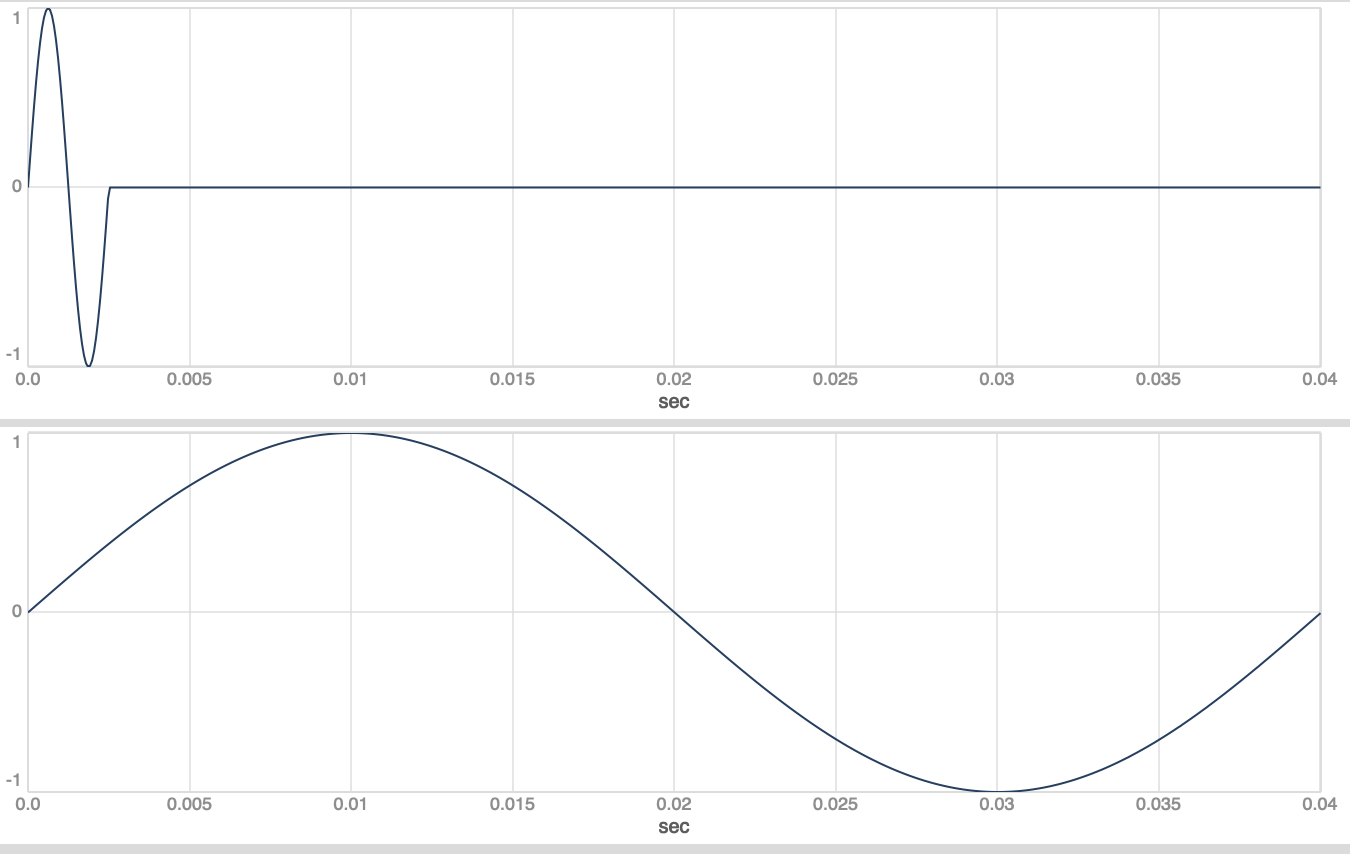
//This stays at 1 after the first complete windowPhase (= the first grain)
windowPhase = (windowSlope * accumulator).clip(0, 1);
window = windowPhase < 1;
sig = sin(grainPhase * 2pi) * window;
[sig, lfo]
}.plot(0.04)
)
- This is messier. I think here the problem is how to get an LFO that’s driven by measurePhase but independent from stepTrigger
(
var rampToSlope = { |phase|
var history = Delay1.ar(phase);
var delta = (phase - history);
delta.wrap(-0.5, 0.5);
};
var rampToTrig = { |phase|
var history = Delay1.ar(phase);
var delta = (phase - history);
var sum = (phase + history);
var trig = (delta / sum).abs > 0.5;
Trig1.ar(trig, SampleDur.ir);
};
var getSubSampleOffset = { |phase, trig|
var slope = rampToSlope.(phase);
var sampleCount = phase - (slope < 0) / slope;
Latch.ar(sampleCount, trig);
};
var accumulatorSubSample = { |trig, subSampleOffset|
var accum = Duty.ar(SampleDur.ir, trig, Dseries(0, 1));
accum + subSampleOffset;
};
{
var measurePhase = (Phasor.ar(0, SampleDur.ir) - SampleDur.ir).wrap(0, 1);
//Would it be possible to insert an LFO that's driven by the measurePhase to modulate trigFreq.kr?
var stepPhase = (measurePhase * \trigFreq.kr(100)).wrap(0,1);
var stepTrigger = rampToTrig.(stepPhase);
var stepSlope = rampToSlope.(stepPhase);
var subSampleOffsets = getSubSampleOffset.(stepPhase, stepTrigger);
var accumulator = accumulatorSubSample.(stepTrigger, subSampleOffsets);
var grainFreq = \grainFreq.kr(200);
var grainSlope = grainFreq * SampleDur.ir;
var grainPhase = (grainSlope * accumulator).wrap(0, 1);
var grain = sin(grainPhase * 2pi);
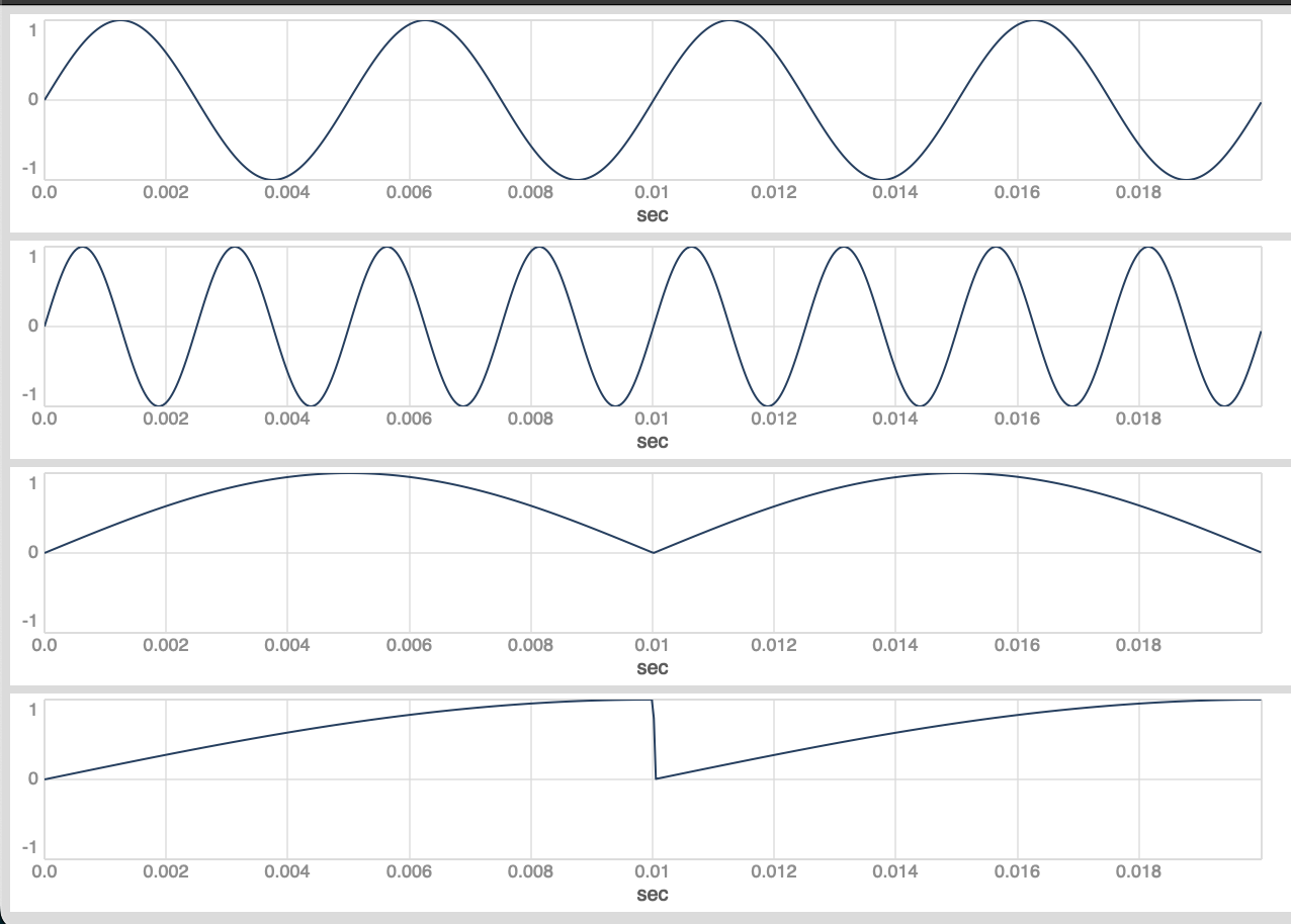
//lfo faster than the stepPhase works
var lfoSlopeA = \trigFreq.kr * SampleDur.ir / 0.25;
//dividing the stepPhase for slower LFOs doesn't work: lfoPhaseB and lfoPhaseC do not reach 1 before the next trigger, which resets them to 0; and the LFO phases are dependent on the accumulator, which counts the stepTrigger, so it's not possible to modulate trigFreq.kr with these LFOs
var lfoSlopeB = \trigFreq.kr * SampleDur.ir/2;
var lfoSlopeC = \trigFreq.kr * SampleDur.ir/4;
var lfoPhaseA = (lfoSlopeA * accumulator).wrap(0,1);
var lfoA = sin(lfoPhaseA * 2pi);
var lfoPhaseB = (lfoSlopeB * accumulator).wrap(0,1);
var lfoB = sin(lfoPhaseB * 2pi);
var lfoPhaseC = (lfoSlopeC * accumulator).wrap(0,1);
var lfoC = sin(lfoPhaseC * 2pi);
[grain, lfoA, lfoB, lfoC]
}.plot(0.02)
)
There are different ways to create subdivided ramps between 0 and 1 from a main phasor. Here are the ones i know:
1.) multiply the main phasor by a ratio and wrap it between 0 and 1
(
{
	var phase, phaseDiv;

	phase = (Phasor.ar(0, \rate.kr(100) * SampleDur.ir) - SampleDur.ir).wrap(0, 1);
	phaseDiv = (phase * \ratio.kr(4)).wrap(0, 1);

	[phase, phaseDiv]

}.plot(0.02)
)
2.) calculate the slope and a trigger from your main phasor. Then run an accumulator and reset it by the trigger, multiply it by the slope and a ratio and wrap or clip it between 0 and 1 (or both). This is what you want to do for your windowPhase (use clip) and grainPhase (use wrap).
(
var rampToSlope = { |phase|
	var history = Delay1.ar(phase);
	var delta = (phase - history);
	delta.wrap(-0.5, 0.5);
};

var rampToTrig = { |phase|
	var history = Delay1.ar(phase);
	var delta = (phase - history);
	var sum = (phase + history);
	var trig = (delta / sum).abs > 0.5;
	Trig1.ar(trig, SampleDur.ir);
};

{
	var phase, slope, trigger, accumulator, phaseDiv;

	phase = (Phasor.ar(0, \rate.kr(100) * SampleDur.ir) - SampleDur.ir).wrap(0, 1);
	slope = rampToSlope.(phase);
	trigger = rampToTrig.(phase);

	accumulator = Duty.ar(SampleDur.ir, trigger, Dseries(0, 1));

	phaseDiv = (slope * \ratio.kr(4) * accumulator).wrap(0, 1);

	[phase, phaseDiv]

}.plot(0.02)
)
3.) calculate the slope of your main phasor. Then run an accumulator but dont reset it by a trigger and multiply it by the slope and a ratio and wrap it between 0 and 1. This is the only way of these three attempts to accumulate a new phasor which is slower then your original one. But the triggered reset is the only way of keeping them in sync.
(
var rampToSlope = { |phase|
	var history = Delay1.ar(phase);
	var delta = (phase - history);
	delta.wrap(-0.5, 0.5);
};

{
	var phase, slope, trigger, accumulator, phaseDiv;

	phase = (Phasor.ar(0, \rate.kr(100) * SampleDur.ir) - SampleDur.ir).wrap(0, 1);
	slope = rampToSlope.(phase);

	accumulator = Duty.ar(SampleDur.ir, 0, Dseries(0, 1));

	phaseDiv = (slope * \ratio.kr(0.5) * accumulator).wrap(0, 1);

	[phase, phaseDiv]

}.plot(0.021)
)
2 Likes
I would suggest to make the phases for your lfos and the phases needed for granulation separate things.
1 Like
Originally, I was hoping to find a way to somehow keep the grain phase and the LFO phase synced to make sure the LFO phase wouldn’t jump to 0 halfway through a grain, but that might just not be possible. Anyway, I learned a lot from this thread.
I would suggest to make sure you get subsample accurate phases for window, carrier and pm modulator and then additionally run a bunch of lfos with subdivisions from a main modulation phaser and attenuate and mix them to modulate your grain params. I was investigating what you have been trying to do for some time, but it wasnt leading to anything useful imo.
I think for slower pulse trains, with trigger rates below 20hz, it might be useful to sync the grain and the LFO phase. But above that, the perceptual advantage is probably minimal.
we are speaking about using LFOs to modulate the trigger frequency, or?
Yes, exactly, I should have specified that
This is a special case. You would need a single sample feedback loop which latches the LFO of your trigger frequency modulation per trigger.
I have been working on one approach in gen~. You trigger a one shot ramp from the language and get a linear ramp between 0 and 1. You can curve that linear ramp (i have used a tunable sigmoid function here) and can set a fixed amount of linear sub ramps between 0 and 1 per event, distributed over the time of the event according to the curve param you set per event. You can get triggers, slopes and durations from these linear sub ramps.
Would like to share a video, but max is 4 mb.
I think the stuff i like is based on triggered events with distributions of sub events and not free running lfos (could be wrong). I think thats the only way which leads to formal structure, but really tricky with audio rate sequencing.
4 Likes
This thing you are working on sounds really fantastic. It’s a pity the forum won’t let you upload the video.
Tbh, I am not sure how Lee Fraser creates these kinds of formal structures with all the constantly evolving micro-events. I think I read that they are using CSound, which I don’t know much about.
The Device is already working fine. Currently the RNBO export to SC needs some love, opened an issue on GitHub. As soon as this is fixed I will create a Ugen.
3 Likes
Looking forward to using it when it’s ready!