RFC: Sweep and Phasor subsample interpolation fixes

This is a Request for Comments (RFC). I’m trying to make it happen on this forum to potentially reach more users. If anyone has comments or thoughts about the format itself, I would suggest making a separate post, to keep this discussion clear.

This discussion started on github: Sweep and Phasor do not wrap properly on inter-sample triggers · Issue #6883 · supercollider/supercollider · GitHub. I will keep this post updated with the state of the discussion as it goes on here on the forum.

The problem

Phasor and Sweep perform linear interpolation to calculate triggers’ subsample offsets, but 1) formulas are wrong and 2) the assumption is incompatible with non-linear signals, e.g. Impulse and LFPulse.

As a result Phasor and Sweep don’t reset precisely when triggered. They are expected to reset to their resetPos (0 for Sweep, and we will use 0 for Phasor too in this post), but they have inaccuracies due to the way they calculate subsample interpolation.

SC defines a trigger as a “transition from non-positive to positive”, that is x[t] is a trigger if x[t-1] <= 0 && x[t] > 0. Continuous signals could have such zero-crossing between samples: imagine a signal that outputs [-1,1,-1,1,...], under the assumption that the signal is linear, we can interpolate and assume the zero crossing happens 0.5 samples before each second sample.

Sweep and Phasor use linear interpolation to estimate inter-sample triggers offset and apply a fraction of their increment. For example, if the increment is 10 and subsample offset is 0.5, they would reset to 5 instead of 0. If subsample offset is 0, they would reset to 10: because the signal zero-crossed 1 sample ago, they have to apply a full increment to the current sample.

This assumption doesn’t hold for Impulse or step-like signals, e.g. [0,1,0,1,...] because the signal is non-linear, but it increments “instantly” from 0 to 1, so the zero crossing happens exactly on the 1 samples (every second sample in the example). Applying linear interpolation would result instead in a subsample offset of 0, i.e. triggers happening on the previous sample (the zeros), and the ugens resetting to 10 instead of 0 (if increment is 10 like in the previous example).

So, linear interpolation is incompatible with impulse or step-like signals. Phasor and Sweep also don’t calculate subsample offset correctly (bugged cpp formula), so the current implementation is wrong for both cases (linear and impulse).

Code examples

Here are some code example to illustrate the situation.
If when running this code the first samples of output look different from the pictures, it’s because of other bugs that got recently fixed on develop.
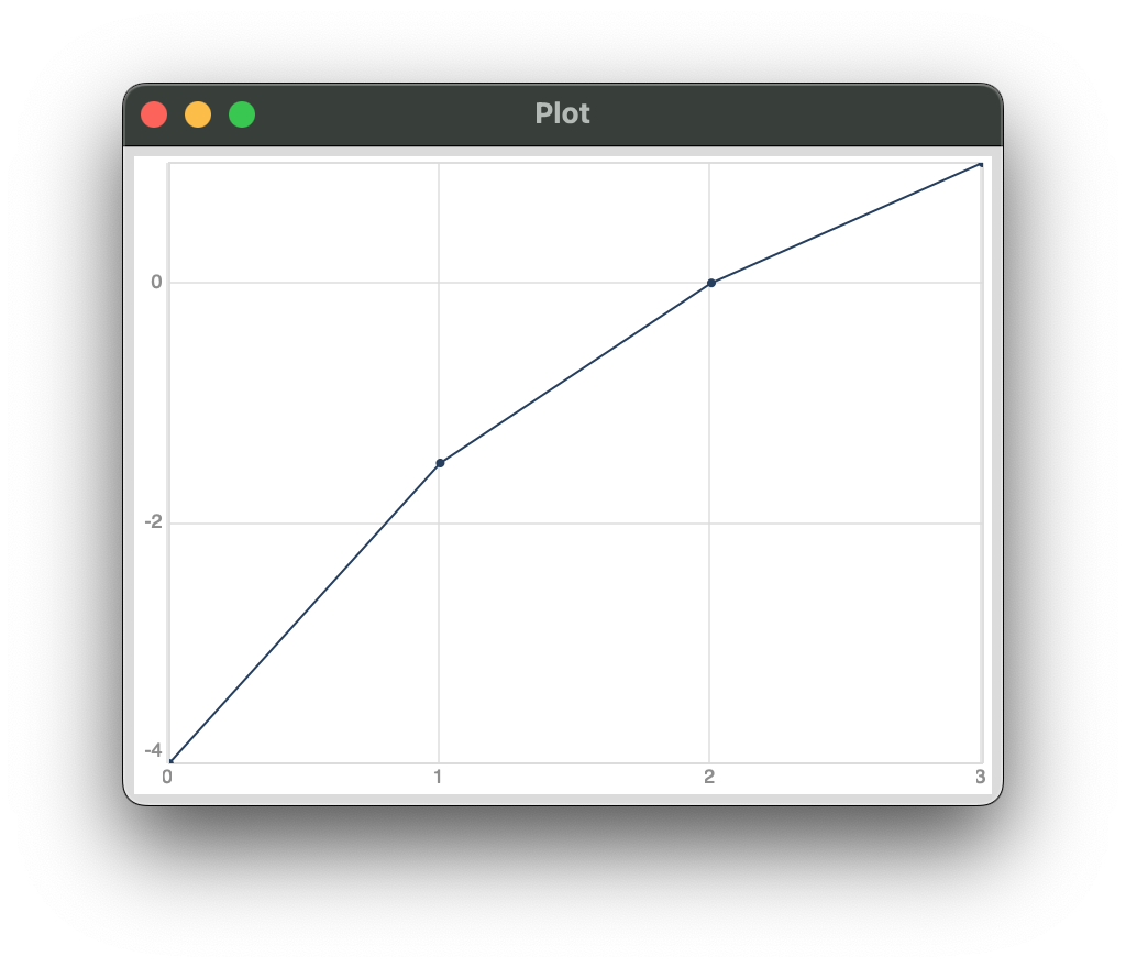
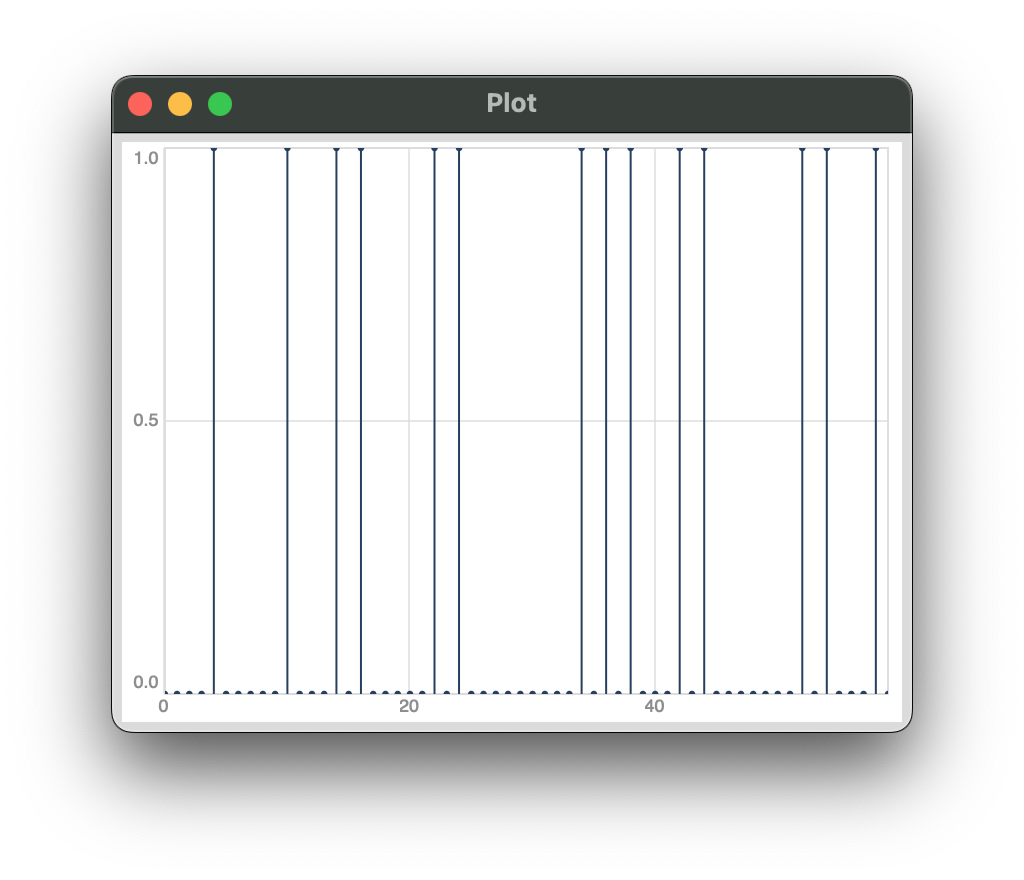
  1. Impulse triggers:
    Phasor resets to 1 instead of 0. Sweep looks correct, but only because linear interp formula (cpp) is wrong
{
	var trig = Impulse.ar(SampleRate.ir/5);
	[Phasor.ar(trig, end: 10), Sweep.ar(trig, SampleRate.ir)]
}.plot(0.0005).plotMode_(\dstems)

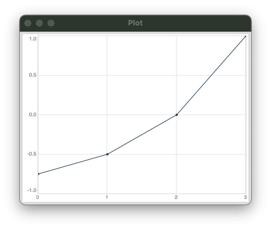
  1. Inter-sample trigger
    To get triggers between samples, we use a Phasor outputting [-0.5, 1.5, -0.5, 1.5, ...]. This results in a trig on samples 0.25, 2.25, 4.25, etc. That is, every other sample, we would expect UGens to reset to 0 and then apply 0.75 increment, since the inter-sample trig happened 0.75 samples earlier.
    Due to errors in the interpolation formula, Sweep resets to 0.25 (= 1 - 0.75) and Phasor to 1.25 (= 1 + 0.25).
    (for more details about how the formulas are wrong, see the github issue linked above)
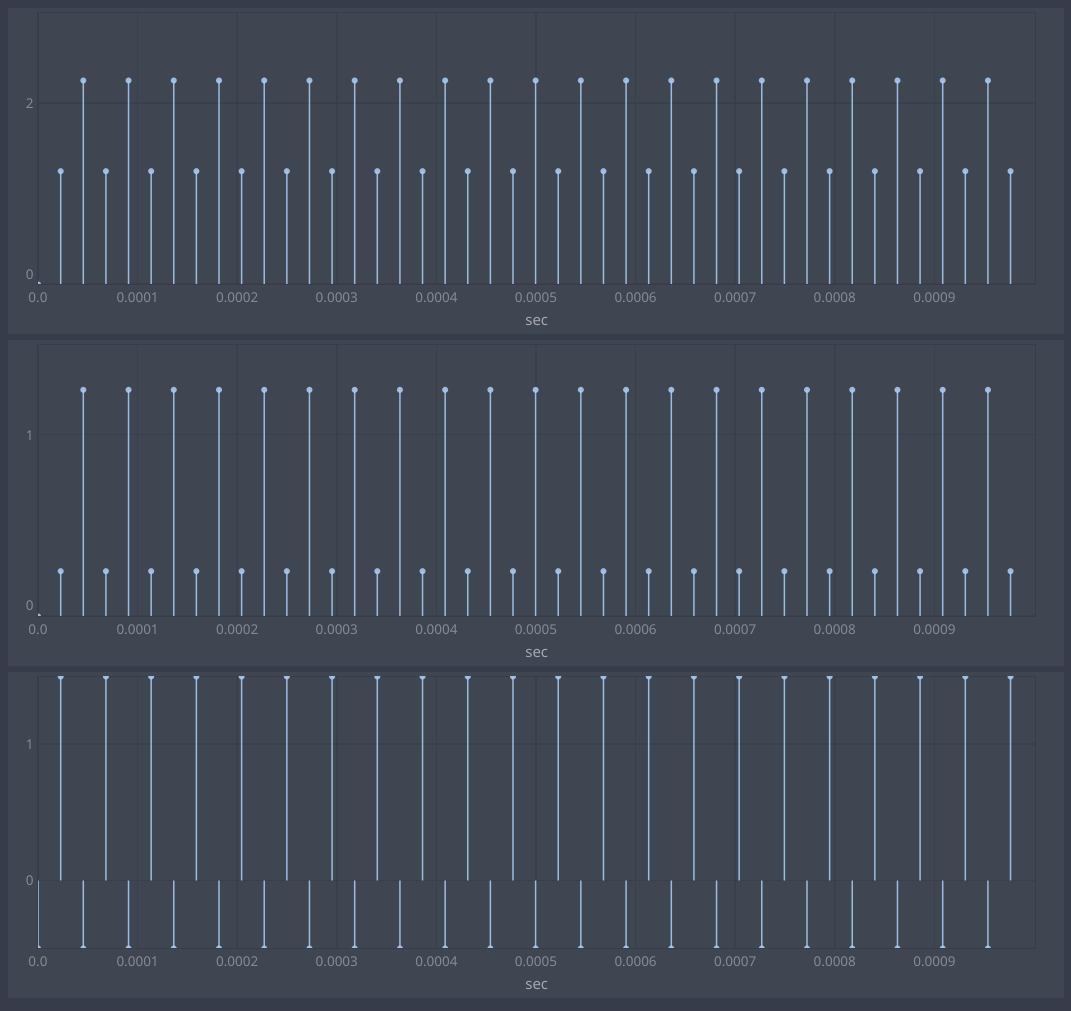
{
	var trig = Phasor.ar(0,2,-1,3) + 0.5; // [-0.5, 1.5, -0.5, 1.5, ...]
	[
		Phasor.ar(trig, 1, 0, 10),
		Sweep.ar(trig, SampleRate.ir), 
		trig
	]
}.plot(0.001, separately: true).plotMode_(\dstems)

// output
// Phasor: [0.0, 1.25, 2.25, 1.25, 2.25, 1.25, 2.25, 1.25]
// Sweep:  [0.0, 0.25, 1.25, 0.25, 1.25, 0.25, 1.25, 0.25]
// trig:   [-0.5, 1.5, -0.5, 1.5, -0.5, 1.5, -0.5, 1.5]

Alternatives for fixing it

We are discussing three alternatives for fixing this behavior. Note that none of these solution is perfectly retro-compatible: we would have in all cases to alter (even if slightly) the output of these UGens. We are talking about changes in the order of sample accuracy, but one never knows how these things amplify when used together in a musical situation.

From the initial discussion on github so far, there was a preference is for option A over the others. On the forum we’ve seen a preference for B, but we’ve found important false positives. Now it seems we are orientating more towards C.

I’m personally biased towards option C. Although I’m trying to be as neutral as possible, I wanted to make this explicit for the reader.

A: add an interp parameter to Sweep and Phasor

Control interpolation explicitly by adding a new interp parameter. It could be set to 0 (no interpolation) by default to support workflow with triggers (arguably the most common), or to 1 (linear interpolation) to maintain the old behavior (although the formula would now be fixed, so it would anyway produce different output).

Pros:

  • no new UGens
  • predictable behavior, controllable by the user
  • works by default with impulses and can be set to interpolate correctly for linear signals

Cons:

  • adding a new argument to a UGen is somehow shady: since there is no server-side spec for UGen inputs, the server doesn’t know how many inputs a UGen reads, and it just allocates as many as a SynthDef requests. Unaware clients would make the server allocate one input too few, and the UGens would then read the extra arg from adjacent buffers (likely their own output).
  • cpp implementation becomes more complex (more cases to handle)

B: turn off interpolation if x[t-1] == 0.f

This fix attempts to detect impulse and step-like signals by checking if their previous sample was exactly 0, and in this case turn off linear interpolation.
A subsequent improvement proposes to turn on interpolation only if x[t-1] < 0.f || (x[t-1] == 0 && x[t-2] < 0.f). Checking for x[t-2] is proposed to further disambiguate between linear and non linear signals.

if (prevtrig <= 0 && curtrig > 0) {
    float offset = 0;
    if (prevtrig != 0 || prevprevtrig < 0) {
        offset = curtrig / (curtrig - prevtrig) * rate;   
    }
    // apply offset to resetPos
}

@mike @jamshark70 I have tried to be succint here, please let me know if I didn’t represent your proposals properly.

Pros:

  • we keep the same UGens and interface: no new UGens, no new parameters
  • UGens now behave correctly with impulse triggers, and interpolate correctly for subsample zero-crossings when x[t-1] < 0
  • Other than false positives, changes in UGen outputs would be only fixes: UGens still interpolate, now with the correct offset, including a null offset for Impulses.

Cons:

  • Has false positives: linear signals that happen to be exactly 0.f would be treated as impulses (no interpolation). Most prominently, a ramp going [1.0, 0.0, 0.1] would be treated as an Impulse by all formulas proposed so far.
  • interpolation can’t be controlled directly by users

C: remove linear interpolation from Sweep and Phasor, and make new dedicated UGens for it (e.g. PhasorL and SweepL)

This fix removes linear interpolation from Sweep and Phasor, and adds new dedicated UGens for it, e.g. SweepL and PhasorL (or Sweep1 and Phasor1).

Pros:

  • predictable behavior: Sweep never interpolates and works correctly with triggers, SweepL always interpolates and works correctly with linear continuous signals
  • new dedicated UGens could also implement more features for subsample accuracy (e.g. linear interpolation of rate as well)

Cons:

  • adding new UGens for a specialized use case: proliferating UGens may overwhelm users.
  • old UGens don’t interpolate anymore, which might “break” old code (old code now produces different output). But apart from their cpp source, these UGens have never “promised” to do interpolation (no mention in schelp docs or code examples), and they have also been doing it wrong for about 20 years without anyone reporting it (to the best of my knowledge).
5 Likes

I’d second your point about overwhelming users with new variants of UGens in suggestion C. However, what about leaving interpolation in Phasor and Sweep as it is and instead creating new variants (don’t know - PhasorN, SweepN or so?) that have interpolation removed. That would at least eliminate the risk of breaking existing user code, wouldn’t it?

I favor B - re: A as I understand it changing the UGen signatures creates problems for people maintaining alternatives to sclang for one…

can you overcome the false positive problem by checking 2 samples back? if the penultimate sample is neither 0.f nor 1.0 then assume its a continuous signal?

philosophically the more complete solution is to ban discontinuous signals and treat triggers as 1 sample ramps always…

Yes – be very careful about that.

@elgiano About false positives – was turning this over in my head, what about this?

Let’s imagine 3 samples, a, b and c (only because it’s easier to type than y(-2), y(-1) and y(0)). C is the trigger sample; b immediately precedes it; and a precedes b.

Interpolation case: b < 0, c > 0. Plot b at x = 0 and c at x = 1. So the fraction of a sample to add to the ramp that’s being triggered is 1 - x where:

(c-b)x + b = 0
x = -b / (c-b)

1-x then = (c-b + b) / (c-b) = c / (c-b)

If b is 0 (the problem case), then c / (c-b) = c/c = 1, so you’d always apply a full sample’s worth of offset, which isn’t desired for impulses.

When do you want the full sample’s worth of offset, when b = 0? When the trigger signal is a straight line. In that case, c = some positive number, b = 0 and a = -c.

  • b = 0, a = 0, subsample proportion should be 0.
  • b = 0, a = -c, subsample proportion should be 1.

So you can negate a, clip it to be within 0 to c, then multiply c / (c-b) by this value over c.

You’d do this only when b = 0. If b is even slightly less than 0, then the subsample offset would be used as is.

Sorry for not making graphs – but I think this would correctly differentiate between the b = 0 cases where you want, or don’t want, to interpolate the subsample offset, without requiring more parameters.

hjh

I think the answer to this is: any signal except for an impulsive signal.

For example, in both of these cases, we’d want the full sample’s worth of offset:

[-4,-1.5, 0.0, 1].plot
[-0.75,-0.5, 0.0, 1].plot

Why assume any impulsive trigger is separated from a previous trigger by at least 2 samples of 0.0?

// dusty impulses
n=30; [n.collect{ 0.5.coin.asInteger }, 0!n].lace(n*2).plot.plotMode_(\dstems)

I’m not sure we can make any assumptions about the signal based on a

I see the reasoning behind that, and I’m aware that my suggestion is attempting a compromise between several hard-edged alternatives for b=0: always impulsive, always linear, or impulsive if a >= 0.

I made an assumption that a discontinuity may be undesired – that is, in prior proposals, if b = 0 and c = 1, then a = 0 vs a = -(10^-30) would be treated as radically different situations, despite the microscopic numeric difference. So I thought, what if they’re not radically different? See what that looks like.

In the common non-impulsive case (a linear ramp providing the trigger signal), b-a and c-b will be equal (apart from rounding error), and my suggestion wouldn’t adjust the subsample offset in that case.

It doesn’t – maybe you overlooked the nonlinearity (which is necessary to keep the subsample fraction between 0 and 1). If a is positive, b is 0, and c is positive, then:

  1. Negate a (now it’s negative).
  2. Clip to the range 0 to c (result: 0).
  3. Divide by c (still 0).
  4. Multiply subsample fraction by this.

So the final subsample fraction in this case would be 0, which is what we want for impulsive triggers.

hjh

I would also say that the only use cases which make sense as a source of time are either impulse like triggers (and maybe gate signals as a special case of impulse like triggers) or linear ramps probably between 0 and 1, where we want to calculate the sub-sample offset. Any other signal doesnt make alot of sense here.

In my opinion there is no need to calculate the sub-sample offset at all for continuous singnals, one could do that manually by deriving triggers and slopes from a continuous signal and add the sub-sample offset to the ramp signal on phase reset. I actually have never seen a piece of code where a user has been using a continuous signal for resetting a ramp signal and relying on sub-sample accurate calculation beeing accurate. The sub-sample calculation has been wrong anyway for 20+ years.

Ah, I see, I took you to mean that b = 0, a = 0. subsample proportion should be 0 was a rule, not an example case.

Tbh I’m still struggling to follow… I think I’d have to see a full implementation (maybe it’s just me).

It seems it wouldn’t work in the example I gave:

[-0.75,-0.5, 0.0, 1].plot

Following your suggested formulation:

a = -0.5, b = 0.0, c = 1;

step = a.neg.clip(0,c) / c
step = -0.5.neg.clip(0,1) / 1 = 0.5

but the proper step in this case should be 1.0.

I agree, although we can’t know whether a signal is continuous or impulsive, unless we make specific assumptions or ask the user to specify (by a UGen arg or separate UGen). So would you say you lean toward option C above?

…but if as @dietcv suggests we are only interested in ramps or impulses then we wouldn’t see your example! Any straight lines passing through 0 will indeed work with @jamshark70’s scheme if I’m understanding correctly, no?

What does this mean in terms of an implementation/solution? The UGen doesn’t get to choose what signals it receives :slight_smile:

AFAICS it means, for any y(0) > 0:

  • If y(-1) > 0, no trigger so subsample anything is irrelevant.
  • If y(-1) < 0, calculate subsample fraction according to the line between (0, y(-1)) and (1, y(0)).
  • If y(-1) = 0:
    • If y(-2) >= 0, assume it’s impulsive (0 subsample fraction).
    • If y(-2) < 0, assume that y(-2) was really meant to be -y(0) and calculate as if it’s a straight line.

… which may be correct. I don’t have a strong opinion whether it’s better, when y(-1) = 0, to have a hard boundary at y(-2) = 0 (as you suggest) or to interpolate based on y(-2) between -y(0) and 0 (my suggestion) – I don’t personally care, and I freely admit that I don’t have a solid mathematical basis for that suggestion, other than a “feeling” that the hard boundary is perhaps too hard. Feel free to ignore that, though!

hjh

Thanks for laying this out, it helps :slight_smile:

  • If y(-2) < 0, assume that y(-2) was really meant to be -y(0) and calculate as if it’s a straight line.

Because know the zero crossing happened at the y(-1), can we simplify this case and just say the step advance is the full fraction? I.e. no need to assume the shape of the signal.

So this is an extension (improvement I think) on option B in the OP. It further disambiguates a continuous from impulsive signal, with the additional cost of one more boolean test and added member variable (x2, i.e. y(-2)).

Thanks everyone for the discussion so far!
I have a couple of points regarding improving the formula and adding a new argument.

about B (improving the formula)

I’m skeptical of solutions like B, because they introduce an extra “hidden assumption” and then they try to work around it. I would prefer we wouldn’t force the assumption at all, and let the user decide if they want interpolation or not. After all, a step function (e.g. y = [-1,0,1]) would be numerically indistinguishable from a ramp, it’s just a matter of what one wants it to be.

I apologize if my examples sound like artificial edge cases, I know I’m making a point only “by principle” and perhaps we could agree on a reasonable compromise. So, is the following code capturing the improved solution B? I would like to update the post.

Interpolate only if:

  • x[-1] != 0
  • x[-1] == 0 and x[-2] < 0
if (prevtrig <= 0 && curtrig > 0) {
    float offset = 0;
    if (prevtrig != 0 || prevprevtrig < 0) {
        offset = curtrig / (curtrig - prevtrig) * rate;   
    }
    // apply offset to resetPos
}

Note that in this case a function giving e.g. y = [0.5, 0, 1] would be treated as an impulse.
Most importantly: a ramp going [0.9, 1, 0, 0.1] would also be treated as an impulse.

about A (adding new argument)

I thought it would be easier than it is. Actually when allocating UGen inputs, the server doesn’t know how many the UGen needs: it gets this number from the SynthDef. This means that a SynthDef can ask the server to create a Sweep with only one input, even if Sweep cpp code will anyway try to read its second input, effectively reading an adjacent buffer.

So, if we add a new argument, old SynthDefs running on a newer scsynth will produce some funny results (interp would be read from a “random” buffer, likely the UGen’s output). I think this is worse in term of retrocompatibility than adding a new UGen: in both cases we have to communicate clearly with alternative clients, but in the “new UGen” case the worst case scenario would be Sweep and Phasor not interpolating anymore, rather than reading an unexpected buffer.

(note: for these kind of scenarios, it would be nice if UGens would define their input/output specs, independently from sclang. There has been a discussion some years ago here)

Thats only true if the rate of the ramp signal is equal to a third of the sampling rate, or?

I hope i read this correctly: a ramp signal which goes exactly from 1 to 0 would line up exactly with the sampling grid (e.g. rate is an integer division of the sampling rate) and therefore doesnt have a subsample offset and should therefore be treated as an impulse.

yes, i think so. But im not sure if we would need the additional ugens.

I mean it shouldn’t be treated as an Impulse, but it would be by the above formula.
Here we have y[0] = 0.1 and y[-1] = 0, so that’s a valid trigger at sample 0. But because y[-2] > 0, the formula wouldn’t it consider a linear ramp, and wouldn’t interpolate, resulting in a 1-sample delay between the triggering ramp and the triggered ramp (when the trigger is 0.1, the triggered one resets to 0).

Even a linear ramp is discontinuous when it wraps. This wouldn’t even be such an abstract use case: a positive ramp resetting exactly to 0.f across one sample is arguably common. Now we would have two different behaviors even for the same kind of signal, depending on its range (if it wraps exactly to 0 or not) and timing (if it wraps exactly on sample boundaries or not).

You are totally right. I have to read the comments once more to understand why we consider to add the additional condition for y[-2] for option B.

Yes, thats the most common use case for a linear ramp between 0 and 1, that it wraps to exactly 0.f in the middle of one sample and not aligns with the sampling grid (it always does when the rate of the ramp is not an integer division of the sampling rate). Therefore the sampled value at the current sample y[0] is not 0.f but the sub-sample offset.
But maybe im misunderstanding what you are saying :slight_smile:

I just dont know it any better: Is there a specific reason why a current value of 0.1 has to be defined as a trigger, other then thats SCs trigger definition. For me triggers have a value of 1.

That’s true; I hadn’t thought of that.

One counterexample is Max’s sah~ (sample-and-hold, basically our Latch), which doesn’t work at all if its input is an unmodified phasor~ and its trigger threshold is 0 (I’ve gotten tripped up over that).

Let’s take for example a trigger signal = Phasor.ar(0, 1, 0, 10) where we know it will always touch but not cross 0 (there’s no fp rounding to worry about). Ideally, then, the second sample would be recognized as a trigger and this trigger would be the tail of a subsample ramp that became > 0 infinitesimally after sample 0, so a full sample’s offset would be added to the triggered UGen’s state, and the result would be indistinguishable from Impulse-triggering it starting with sample index 0.

So then my questions would be (and I don’t have answers to these at the moment, open to suggestions):

  • Does this usage of Phasor as a trigger have advantages over other trigger sources? (I.e., is there maybe a better way to write that?)
  • Is there a way to hack the Phasor signal to work with the approach-B logic?

A trigger is defined as a transition from nonpositive to positive. 0.00001 can be a trigger – and it has to be, for this discussion of ramps-as-triggers to be valid at all.

hjh

where is this defined? It seems to me thats not obvious. At least from my research and speaking to people working professionally on dsp devices.

Im probably wrong but i would assume:

  • for the single-sample impulse case with [0, 1] we want a trigger on the current sample
  • for the linear ramp between 0 and 1 case with [1, 0] we want a trigger on the current sample
  • for the linear ramp between 0 and 1 case with [1, 0.1] we want a trigger on the current sample and calculate the sub-sample offset

But im happy with option C anyway :slight_smile:
For deriving sub-sample accurate events from a scheduling phasor for example for granulation you could just calculate the sub-sample offset yourself (its just one division) and add it on phase reset and when wanting to improve the overall sound of hard sync of an oscillator, sub-sample accuracy does this considerably but only to an extend which is interesting, if you combine that with further anti-aliasing methods like polyblep. I cant think of any other use cases.

If you’re looking for an “Audio triggers” topic help file, there isn’t one.

The source code is pretty clear: curtrig > 0.f && prevtrig <= 0.f means nonpositive to positive. TriggerUGens.cpp has 42 matches for “prevtrig <= 0” and I’m sure there are more in other UGen files.

7 help files mention “nonpositive”:

./Classes/TExpRand.schelp:11:trigger signal changes from nonpositive to positive values
./Classes/Trig.schelp:9:When a nonpositive to positive transition occurs at the input, Trig
./Classes/TIRand.schelp:11:trigger signal changes from nonpositive to positive values.
./Classes/Dreset.schelp:13:a demand or any other UGen. When crossing from nonpositive to positive, it resets the first argument.
./Classes/Trig1.schelp:9:When a nonpositive to positive transition occurs at the input, Trig1
./Classes/TRand.schelp:11:trigger signal changes from nonpositive to positive values.
./Classes/RandSeed.schelp:9:When the trigger signal changes from nonpositive to positive, the synth's

As for obviousness, I find 0.0 to be less arbitrary than, for instance, the analog modular convention placing the trigger threshold at 1V.

… sure. In this case, there are only two possibilities:

  • y[-1] < 0, y[0] > 0: Subsample offset is based on x where (y[0] - y[-1]) * x + y[-1] = 0. This is unambiguous.
  • y[-1] = 0, y[0] > 0: This divides into three cases.
    • If y[-2] < 0, then we can be sure that the signal is ramping, and the subsample offset should be a full sample. Note: If a phasor is the most likely input, then the slope between y[-2] and y[-1] equals that between y[-1] and y[0] (so Mike’s [-0.5, 0.0, 1.0] case is unlikely to occur in the wild).
    • If y[-2] == 0, then it’s definitely an impulse (0 offset).
    • If y[-2] > 0, then it gets tricky because it could be an impulse or it could be a ramp with a lower bound of 0 (where the subsample offset should be a full sample).

I don’t think there’s a good way to disambiguate the last bit. I’d thought about checking y[-2] - y[-3] for being positive, but that would be true for Impulse.ar(SampleRate.ir * 0.5) also.

So I’d go for option C then as well.

hjh

That was a typo – that branch should have been y[-2] > 0. I’ve corrected it above.

Logically it would have been possible to work that out – there was a branch for y[-2] < 0, one for == 0, and then a second y[-2] < 0 – so, obviously, one of those was wrong.

Sorry for confusion. The version above should be correct.

hjh