I’m wondering if there’s a way to do an inverse conversion to derive a saw/ramp wave from a sinewave. I’m thinking there might be a way to do an inverse of:
(
{
var phasor, sine, freq=100;
phasor = Phasor.ar(0, freq*SampleDur.ir)*2-1;
sine = cos(pi*phasor);
[phasor, sine];
}.plot(minval: -1, maxval:1, duration:0.1);
)
My creative studies degrees sadly didn’t cover math, so I’ve been bumping around mostly in the dark trying to find a way to covert it back. This is the best I’ve been able to get so far:
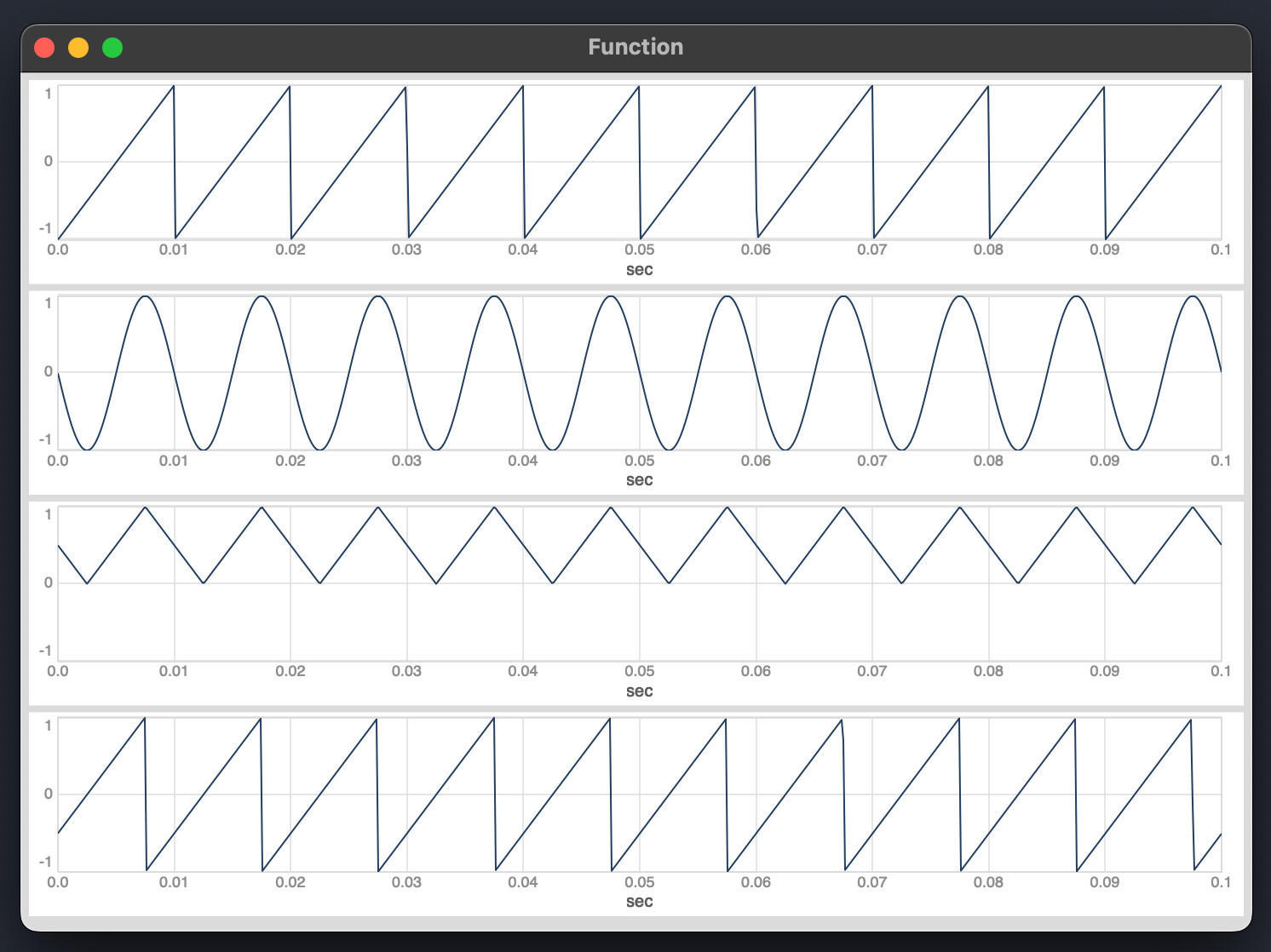
(
{
var phasor, sine, tri, trg, saw, freq=100;
	phasor = Phasor.ar(0, freq*SampleDur.ir)*2-1; //starting phasor
	sine = sin(pi*phasor); //phasor to sine
	tri = (asin(sine)/pi)+0.5; //unipolar triangle
	trg = (tri > 0.9999) + (tri < 0.0001); //triggers to toggle a Select
	saw = (Select.ar(ToggleFF.ar(trg), [tri, tri.neg])).neg; //back to saw
	[phasor, sine, tri, saw];
}.plot(minval: -1, maxval:1, duration:0.1);
)
While this mostly works (the phase difference between the original and the output doesn’t matter for my uses), it only works with a pure waveforms that have a predictable amplitude range. I’m hoping to find something that I can use on signals with a dynamic and unpredictable amplitude range. The thresholds I’m using to switch between waveforms won’t work in those cases.
Another way to think about the flip-flop trigger is: trigger when the triangle wave changes direction.
The simplest concept of “direction” here is a two-point difference, HPZ1.ar(tri). Then sign(HPZ1.ar(tri)) is +1 when it’s moving up, and -1 when it’s moving down.
When this value changes, then flipflop. So trg = HPZ1.ar(sign(HPZ1.ar(sig))).abs > 0. I think… not tested. This shouldn’t depend on the sine’s amplitude.
But if the sine’s amplitude is < 1.0, then the triangle won’t span the full 0.0-1.0 range. I don’t have an answer for that.
An alternate approach is: a sine oscillator depends on a phasor anyway. So, just keep access to the phasor from the beginning?
I’m actually imagining a scenario where my starting point is a sine wave, or a sinusoidal signal, from which I’m trying to derive a linear saw/ramp, so there’s no original saw. I was using the phasor → sine wave conversion as a way to try and understand the inverse transformation.
HPZ1 does work very well in this controlled instance, thanks. I’ll try and throw a more varied signal at this tonight.
could you elaborate why you would need to derive a saw from sine?
As @jamshark70 already pointed out, it would probably make more sense to start with a linear phase signal to drive your sine oscillator and be able to additionally get a bipolar saw oscillator if needed.
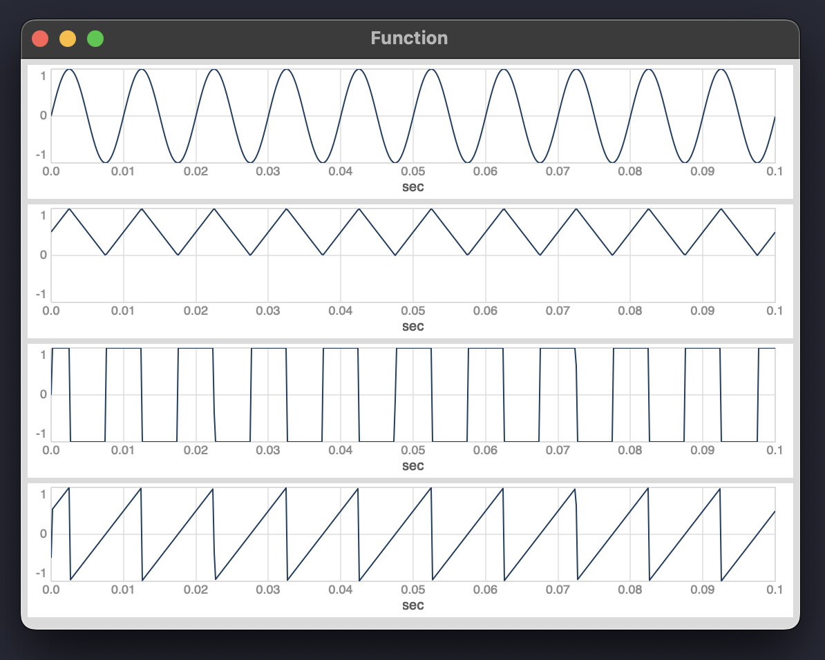
(
{
	var phase = Phasor.ar(DC.ar(0), 100 * SampleDur.ir);
	var sine = SinOsc.ar(DC.ar(0), phase * 2pi);
	var saw = phase * 2 - 1;
	[sine, saw];
}.plot(0.021);
)
Part of what I was hinting at is that most sine oscillators are based on a phasor underneath – just because you don’t see the phasor in the SynthDef, doesn’t mean there is no phasor.
The one exception would be a complex-multiplication sine generator, where you calculate the complex number corresponding to a rotation of x radians per sample, and then raise this to integer powers. If you do it with single sample feedback (tricky in SC except for DynGen or similar UGens), then you’d get sinusoidal motion without an underlying phasor.
I’m imagining a scenario where I have an arbitrary signal (live audio input, sampled audio) that I want to able to derive a saw for wide further waveshaping potential. A saw seems to me the best starting point for deriving a wide range of wave shapes, and for indexing into wavetables, but I’m open to suggestions.
The idea started with the Rossum Panharmonium, which has waveform morphing (sine to tri to saw to pulse) on the conversion back from the FFT. I was particularly interested in the timbral quality of the saw on the Panharmonium, and I wanted to find a simple way to derive a similar linear wave for use in any scenario.
Jamshark70’s suggestion of slope detection driving a signal switch is an excellent one, and does seem to work quite well so far.
For an arbitrary signal, there’s no guarantee of an inverse function – even with a sine, except for -1 and +1, every other value appears twice during the cycle, so the arcsin only spans ±0.5pi, not ±pi – the flip flop logic is already a clue that the operation is a bit of a problem.
Live audio input may be messier than you expect. Paul’s suggestion may be better, in that case: try some pitch and/or autocorrelation analysis to at least estimate the cycle duration for the sawtooth, and maybe augment that by syncing to zero crossings…?
Pitch analysis in SC (AFAIK) assumes a monophonic signal, so keep that in mind as well.
You’re very correct on that front. I’m not against mess and chaos, but it quickly devolves to a not so useful chaos as I move away from more controlled instances.
Beyond my use case scenario, I am very interested in these kinds of conversions, and whether it is actually possible. I’ve learned a good deal from reading through the posts here from @dietcv on different waveshaping approaches, and understanding what generates a certain kind of waveform is very useful to find other wave forms that beyond the standard wave forms.
Is it even possible to use a transfer function to get a saw from a sine? I’ll have to give that a go.
If you start from a phase signal (i cant see any point in doing the opposite), what you are describing is basically classic phase distortion synthesis using a segmented non-linear transfer function with adjustable breakpoint. The waveform itself might look different but the spectrum is similiar.
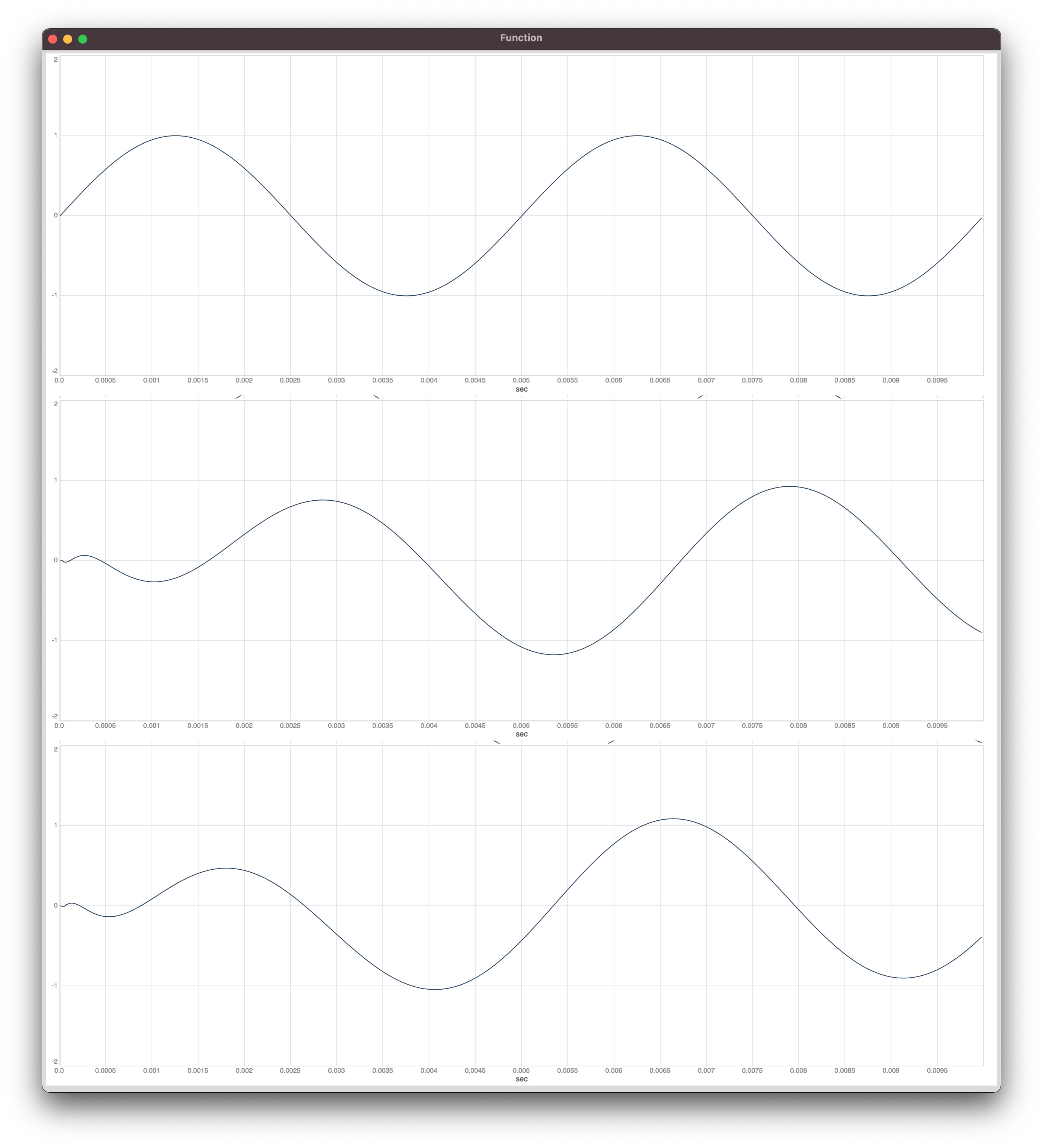
You can also use a Hilbert transform to convert one sine wave signal into two sine wave signals with a 90-degree phase shift from each other, aka an analytic signal, then use the atan2 function to convert real+imaginary components to phase, giving you a saw wave.
(
{
	var sig;
	sig = SinOsc.ar(XLine.ar(200, 3000, 0.1));
	sig = Hilbert.ar(sig);
	sig[0].atan2(sig[1]);
}.plot(0.1);
)
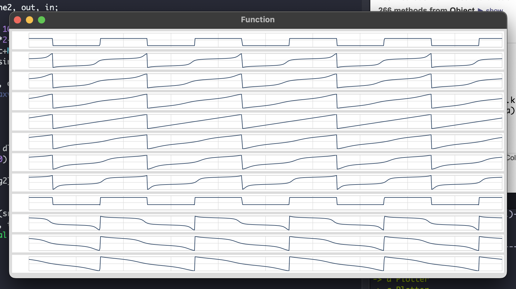
This is good stuff. I played around with the phase of the second sine wave, and there’s some interesting waveforms adjacent to that perfect saw, which helped me understand what’s happening:
(
{
	var phasor, sine, out;
	out = [];
	phasor = Phasor.ar(0, 100*SampleDur.ir);
	sine = 1-cos((phasor*2-1)*pi)-1;
	for(0, 11, { arg i;
		var subSine = 1-cos(((phasor+(0.0625*i))*2-1)*pi)-1;
		out = out.add(sine.atan2(subSine)/pi);
	});
	out;
	}.plot(minval:-1, maxval: 1, duration:0.05);
)
Thats nice - just learned yesterday about Hilbert transformation while looking into freq shifters.
Note that Hilbert uses internally a IIR filter which introduces frequency-dependent phase delays to the signal - so if you want to do some phase alignment, make sure to use the the first output of the Hilbert transformation, which will be delayed (since it also passes the filter) and also introduces some artifacts due to the approximation of the filter (see e.g. the amplitude).
(
{
	var sig = SinOsc.ar(200.0);
	var hilbert = Hilbert.ar(sig);
	[sig] ++ hilbert
}.plot;
)
do methods alternative to FFT implementations provide more optimized delay results? Meaning, can you get a similar effect without the 1024/2048 sample delay necessary for effective phase shifting using HilbertFFT?