Advanced Synthesis - Oscillator Sync

im not familiar with C++ and wanted to make a smooth step with DSP into that.

Oh sure. It’s just that trying to implement any algorithm that relies upon sample level code is always going to be a challenge in SuperCollider as it doesn’t support that very well.

You could investigate Faust. It’s a lot easier to wrap your head around and can generate UGens.

I have already been working for the last months in gen. There is no need to switch to faust.

Faust would allow you to create SuperCollider UGens.

You can use RNBO to export gen code and create SC ugens

I have succesfully implemented the anti aliased saw with hard sync from the go book, i have posted above:

(
var rampToTrig = { |phase|
	var history = Delay1.ar(phase);
	var delta = (phase - history);
	var sum = (phase + history);
	var trig = (delta / sum).abs > 0.5;
	Trig1.ar(trig, SampleDur.ir);
};

var rampToSlope = { |phase|
	var history = Delay1.ar(phase);
	var delta = (phase - history);
	delta.wrap(-0.5, 0.5);
};

var getSubSampleOffset = { |phase, trig|
	var slope = rampToSlope.(phase);
	var sampleCount = phase - (slope < 0) / slope;
	Latch.ar(sampleCount, trig);
};

var hardSyncSubSample = { |carrierFreq, syncFreq|

	var syncPhase, syncTrigger, syncSubSampleOffset;
	var carrierSlope, carrierPhaseCurrent, carrierPhaseLast;
	var loopSyncSubSample, mix, triggerTrans;
	var carrierPhaseBeforeTrans, carrierPhaseAfterTrans;
	var replaceCarrierPhaseBeforeTrans, replaceCarrierPhaseAfterTrans, sig;

	syncPhase = (Phasor.ar(DC.ar(0), syncFreq * SampleDur.ir) - SampleDur.ir).wrap(0, 1);
	syncTrigger = rampToTrig.(syncPhase);
	syncSubSampleOffset = getSubSampleOffset.(syncPhase, syncTrigger);

	carrierSlope = carrierFreq * SampleDur.ir;
	carrierPhaseCurrent = (Phasor.ar(syncTrigger, carrierSlope) + (carrierSlope * syncSubSampleOffset)).wrap(0, 1);
	carrierPhaseLast = Delay1.ar(carrierPhaseCurrent);

	loopSyncSubSample = (carrierPhaseCurrent.wrap(-0.5, 0.5) + (carrierSlope * 0.5)) / carrierSlope;
	mix = Select.ar(syncTrigger, [loopSyncSubSample, syncSubSampleOffset]);
	triggerTrans = (mix >= 0) * (mix < 1);

	carrierPhaseBeforeTrans = (carrierPhaseLast - (carrierSlope * mix)).wrap(0, 1);
	carrierPhaseAfterTrans = (carrierPhaseCurrent - (carrierSlope * (mix - 1))).wrap(0, 1);

	replaceCarrierPhaseBeforeTrans = Select.ar(triggerTrans, [
		carrierPhaseCurrent,
		carrierPhaseBeforeTrans
	]);

	replaceCarrierPhaseAfterTrans = Select.ar(triggerTrans, [
		carrierPhaseCurrent,
		carrierPhaseAfterTrans
	]);

	// throw in unit shapers here!!!!!

	sig = LinXFade2.ar(
		replaceCarrierPhaseBeforeTrans,
		replaceCarrierPhaseAfterTrans,
		mix.clip(0, 1) * 2 - 1;
	);

	sig * 2 - 1;
};

{
	var freq, fmod, fmFreq, sig;
	fmFreq = \fmFreq.kr(3);
	fmod = SinOsc.ar(fmFreq) * \index.kr(0);
	fmod = fmod - OnePole.ar(fmod, exp(-2pi * fmFreq * SampleDur.ir));
	freq = \freq.kr(270);
	sig = hardSyncSubSample.(freq + (freq * fmod), \syncFreq.kr(50));
	sig = LeakDC.ar(sig);
	sig!2 * 0.1;
}.play;
)

here an audio example of a naive phasor at 2000 hz and the subsample accurate phasor at 2000 hz

Here a plot for carrier freq at 273 hz and sync freq at 517 hz for the anti-aliased and the naive version:
grafik
grafik

I think adding 2x oversampling would already be enough.

1 Like

Hi dietcv.

Sorry for replying to this such a long time afterwards.
Did you ever end up porting Rung Divisions to SC?
I’m a huge fan of anything Runglery and I was very excited about the ideas in the Rung Divisions module but I’m not much of a modular guy. Would be super cool to get something like it as a tool to work with in SC.

Hey, thanks for the interest. The device has two main sections, the clock divider and the shift register part. I have been able to implement all of the control params from the original device. For a SC implementation you would have to decide if you want to hardcode the 3-bit or the 8-bit output to self modulate the main clock in a feedback loop. Haven’t made that decision yet. The clock divider combines a number of hardcoded divisions at the output bus with logical operations. With triggers that’s trivial, but I wanted to implement the combination of linear ramps instead of triggers. The combination of ramps at the output bus works already, but I have to figure out how make sure the phase at the output bus isn’t distorted if you add or remove divisions, I additionally think it makes no sense to hardcode the divisions like it’s done in the original device but let the user decide the division factors (when dividing ramps these can be non integer values). But beside these design decisions I’ve underestimated the work which has to be done in c++ to be able to export from RNBO to sc. I have no idea how long this would take to implement. Speaking of runglers, Im also working on a blippo box implementation with anti-aliased oscs and svfs filters with non-linearities in the feedback path. So a bunch of stuff as soon as the export does work. But chances are that I won’t be successful with that.

2 Likes

I think you are doing great work and I just want to give you praise and encouragement. Can I follow you on some kind of Git site?

1 Like

Hi @dietcv,

i was trying out your sync implementation and was using it to drive the phase of a simple SinOsc. The resulting sound seems buzzy, compared to a simple Phasor. I’m not sure i understand why this is the case, given that the difference, in my understanding, being the subsample accuracy of the driving ramp?
Here’s the modified example:

(
var rampToTrig = { |phase|
	var history = Delay1.ar(phase);
	var delta = (phase - history);
	var sum = (phase + history);
	var trig = (delta / sum).abs > 0.5;
	Trig1.ar(trig, SampleDur.ir);
};

var rampToSlope = { |phase|
	var history = Delay1.ar(phase);
	var delta = (phase - history);
	delta.wrap(-0.5, 0.5);
};

var getSubSampleOffset = { |phase, trig|
	var slope = rampToSlope.(phase);
	var sampleCount = phase - (slope < 0) / slope;
	Latch.ar(sampleCount, trig);
};

var hardSyncSubSample = { |carrierFreq, syncFreq|

	var syncPhase, syncTrigger, syncSubSampleOffset;
	var carrierSlope, carrierPhaseCurrent, carrierPhaseLast;
	var loopSyncSubSample, mix, triggerTrans;
	var carrierPhaseBeforeTrans, carrierPhaseAfterTrans;
	var replaceCarrierPhaseBeforeTrans, replaceCarrierPhaseAfterTrans, sig;

	syncPhase = (Phasor.ar(DC.ar(0), syncFreq * SampleDur.ir) - SampleDur.ir).wrap(0, 1);
	syncTrigger = rampToTrig.(syncPhase);
	syncSubSampleOffset = getSubSampleOffset.(syncPhase, syncTrigger);

	carrierSlope = carrierFreq * SampleDur.ir;
	carrierPhaseCurrent = (Phasor.ar(syncTrigger, carrierSlope) + (carrierSlope * syncSubSampleOffset)).wrap(0, 1);
	carrierPhaseLast = Delay1.ar(carrierPhaseCurrent);

	loopSyncSubSample = (carrierPhaseCurrent.wrap(-0.5, 0.5) + (carrierSlope * 0.5)) / carrierSlope;
	mix = Select.ar(syncTrigger, [loopSyncSubSample, syncSubSampleOffset]);
	triggerTrans = (mix >= 0) * (mix < 1);

	carrierPhaseBeforeTrans = (carrierPhaseLast - (carrierSlope * mix)).wrap(0, 1);
	carrierPhaseAfterTrans = (carrierPhaseCurrent - (carrierSlope * (mix - 1))).wrap(0, 1);

	replaceCarrierPhaseBeforeTrans = Select.ar(triggerTrans, [
		carrierPhaseCurrent,
		carrierPhaseBeforeTrans
	]);

	replaceCarrierPhaseAfterTrans = Select.ar(triggerTrans, [
		carrierPhaseCurrent,
		carrierPhaseAfterTrans
	]);

	// throw in unit shapers here!!!!!

	sig = LinXFade2.ar(
		replaceCarrierPhaseBeforeTrans,
		replaceCarrierPhaseAfterTrans,
		mix.clip(0, 1) ;
	);

	sig;
};

{
	var freq, fmod, fmFreq, sig;
	
	freq = MouseY.kr(1,1000,1);
	
	sig = Select.ar(MouseX.kr(0,1).round(1),SinOscOS.ar(0, [Phasor.ar(0,freq/s.sampleRate),hardSyncSubSample.(freq,0)]*2-1)); //switch between clean and noisy signal
	
	sig = LeakDC.ar(sig);
	sig!2 * 0.1;
}.play
)

Thanks so much for your invaluable work!

1 Like

Lets have a closer look what the patch actually does.

An ideal phasor has infinite resolution and at the moment it wraps around moves instantly from 1 to 0 (red). In digital software the resolution of the phasor is determined by the sample rate, it increments for every sample by one step (green) and has to move continously from one step to the other over the duration of one sample (blue).

At the moment it wraps around it needs one sample to go from the last value before the wrap to the next value after the wrap (grey region). The value before the wrap should ideally be 1 and the value after the wrap should ideally be 0, but the actual values depend on the relative alignment of the phasors wrap with the sampling grid, therefore the phasor enters and exits the transition sample (grey region) with a deviation to the ideal values. These deviations to the ideal values are not symmetrical and therefore introduce irregular harmonic periods and cause the aliasing.

The idea of the patch is to make the phasors wrap which is a tiny ramp over the duration of one sample independent from the sampling grid (grey region) and instead placing it exactly centered on the phasors ideal wrap (red) to make the entry and exit points of the phasors wrap (grey region) always symmetrical (green).

I have to wrap it up for now haha, this took longer than i thought :sleeping:
I will add more information tomorrow.
But here is already an implementation of the phasor with anti-aliasing without hardsync.
If we have a good understanding of the basic patch we can move on to the hard sync and figure out your question.

(
var phasorAntiAliased = { |freq|

	var slope, phase;
	var loopSubSample, detectTrans;
	var phaseBeforeTrans, phaseAfterTrans;
	var replacePhaseBeforeTrans, replacePhaseAfterTrans;

	slope = K2A.ar(freq) * SampleDur.ir;
	phase = Phasor.ar(DC.ar(0), slope);

	loopSubSample = phase.wrap(-0.5, 0.5) + (slope * 0.5) / slope;
	detectTrans = (loopSubSample >= 0) * (loopSubSample < 1);

	phaseBeforeTrans = Select.ar(slope < 0, [
		1 - (slope * 0.5),
		slope * 0.5
	]);

	phaseAfterTrans = Select.ar(slope < 0, [
		slope * 0.5,
		1 - (slope * 0.5)
	]);

	replacePhaseBeforeTrans = Select.ar(detectTrans, [
		phase,
		phaseBeforeTrans
	]);

	replacePhaseAfterTrans = Select.ar(detectTrans, [
		phase,
		phaseAfterTrans
	]);

	LinXFade2.ar(
		replacePhaseBeforeTrans,
		replacePhaseAfterTrans,
		loopSubSample.clip(0, 1) * 2 - 1
	);

};

{
	var sig;
	sig = phasorAntiAliased.(\freq.kr(4000));
	sig = LeakDC.ar(sig);
	sig!2 * 0.1;
}.play
)
1 Like

Thanks a lot @dietcv for the in depth explanation so far! Looking forward to see how this triggerable ramp works as a driving phasor for oscillators.
Also i wonder, apart from the envisioned & implemented triggering for the hardsync, in what way it differs regarding antialiasing / subsample accuracy from this previous method you had developed (which btw works perfectly as a driving ramp for the sine)?

({var rampToSlope = { |phase|
	var delta = Slope.ar(phase) * 1/s.sampleRate;
	delta.wrap(-0.5, 0.5);
};

var rampToTrig = { |phase|
	var history = Delay1.ar(phase);
	var delta = (phase - history);
	var sum = (phase + history);
	var trig = (delta / sum).abs > 0.5;
	Trig1.ar(trig, 1/s.sampleRate);
};

var multiChannelTrigger = { |numChannels, trig|
	numChannels.collect{ |chan|
		PulseDivider.ar(trig, numChannels, numChannels - 1 - chan);
	};
};

var getSubSampleOffset = { |phase, trig|
	var slope = rampToSlope.(phase);
	var sampleCount = phase - (slope < 0) / slope;
	Latch.ar(sampleCount, trig);
};

var accumulatorSubSample = { |trig, subSampleOffset|
	var accum = Duty.ar(1/s.sampleRate, trig, Dseries(0, 1));
	accum + subSampleOffset;
};
{
	
var freq =  MouseY.kr(80,1000,1);
var phasor= Phasor.ar(0,freq*SampleDur.ir);
var slope = rampToSlope.(phasor);
var trigger = rampToTrig.(phasor);
var subSampleOffset = getSubSampleOffset.(phasor, trigger);
var accumulator =  accumulatorSubSample.(trigger, subSampleOffset);
	
sin((freq * accumulator*SampleDur.ir).wrap(0, 1)*2pi)*0.2
}
}.play)

Lets figure out where the difference between these two approaches is.

Lets start with subsample accurate events from phasors for now (this really took me some time to think through, so we can discuss the other approach in the upcoming days and then finally come to your questions haha).

For scheduling events with continous waveforms you need a carrier phase which should reset to zero whenever your scheduling phase completes a cycle. An implementation of this naive hard sync causes a jump in the phase of the carrier whenever the scheduler completes a cycle. This jump in phase leads to a hard edge in the carrier waveform and therefore causes harsh aliasing noise. The first step of getting rid of this hard edge whenever the scheduler forces the carrier to wrap around is to fade out the carrier waveform at the moment the sync happens by applying a window function. This is called windowed sync and is the basic concept of granulation.

In the context of granulation you have a grain scheduler, a phasor going from 0 to 1 and you derive triggers from it to schedule your grain events by calculating the delta of your phasors slope to figure out when the absolute delta is above a certain threshold (the moment the grain scheduler wraps) to reset your carrier phase and applying a window function to fade out the carrier waveform at exactly that moment to smooth out the hard edge the reset causes.

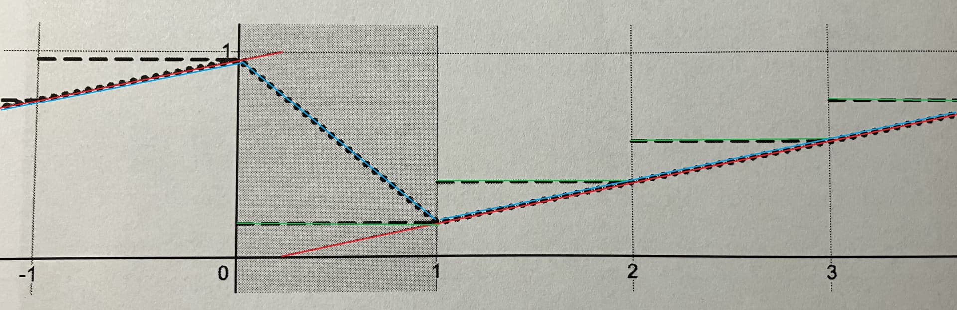
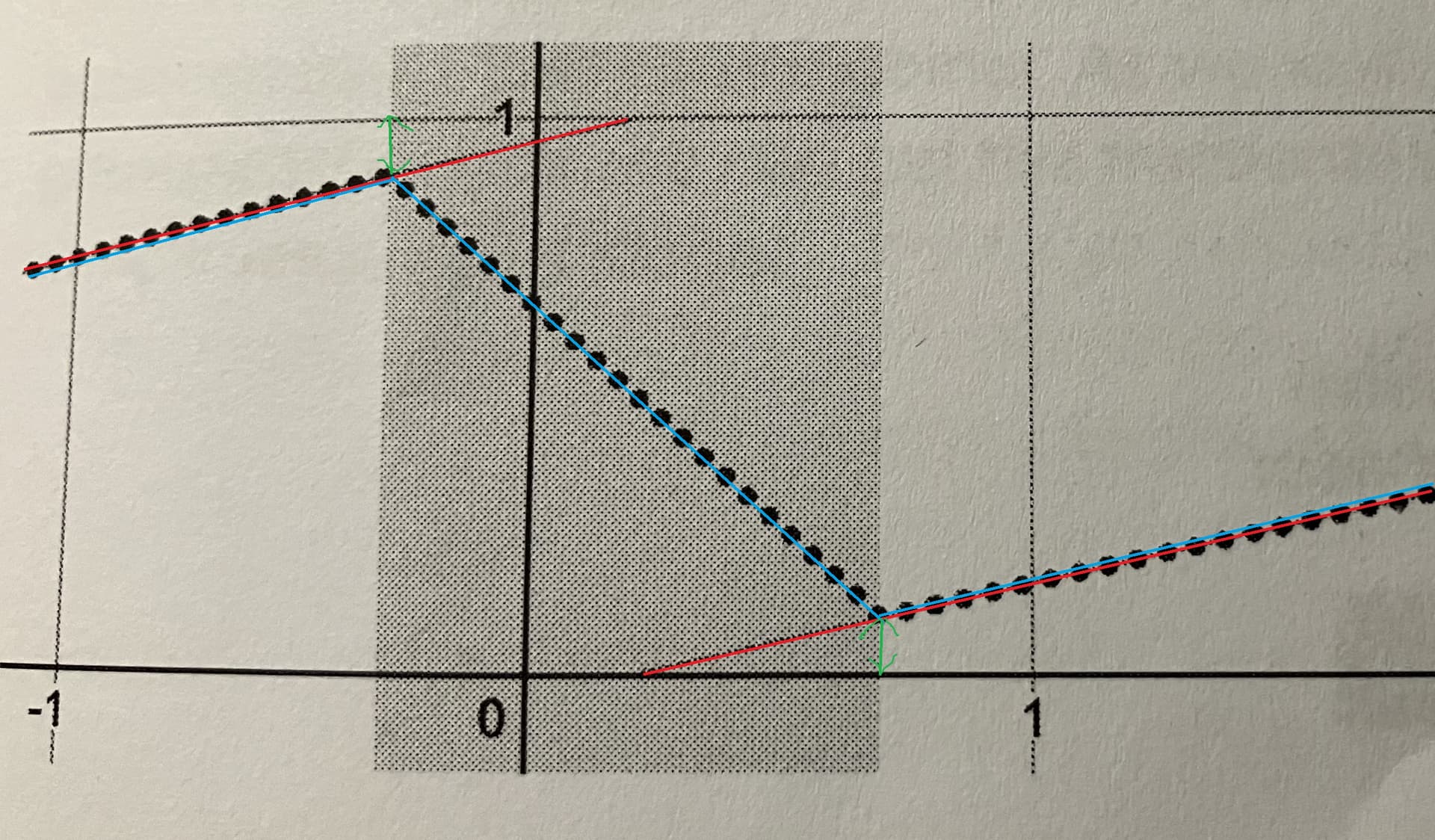
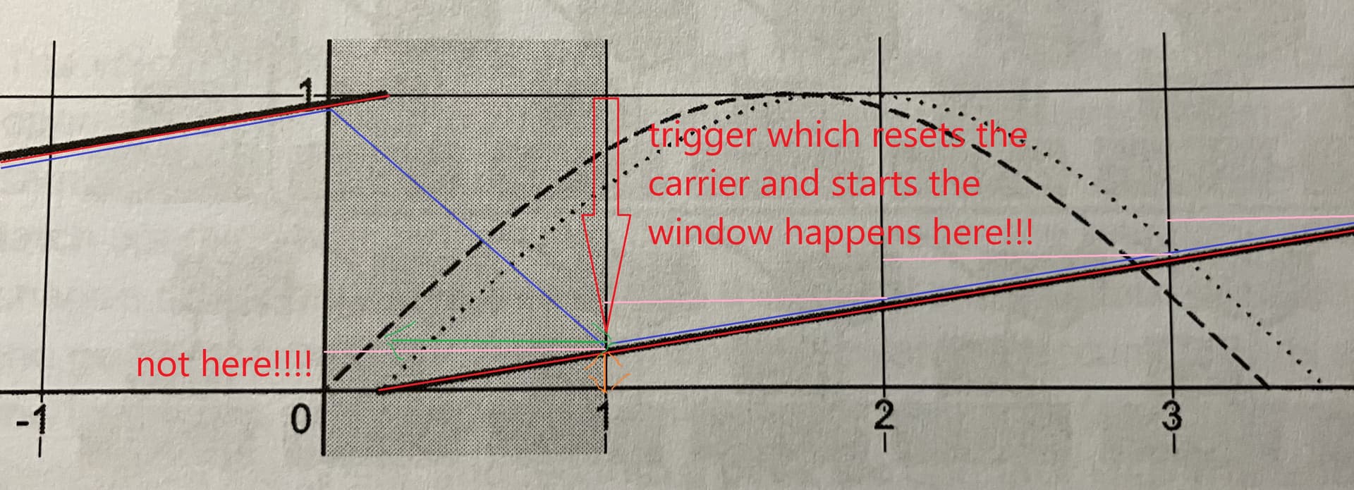
The ideal scheduling phasors wrap (red) happens somewhere between one sample frame and the next (grey region). Calculating the scheduling phasors slope by taking its sample values from the last sample frame and its current sample frame (pink) and to look if this delta is above a certain threshold derives a trigger from the scheduling phasor (blue) which resets the carrier phase exactly to zero at the actual scheduling phasors wrap (marked by the red arrow) and schedules a window function starting from zero at exactly that moment (the dashed line from the book is a mistake IMO). But within that sample frame, where the actual scheduling phasor wraps the sample value is slightly above zero, it deviates from zero by a small amount (orange) and the ideal scheduling phasors wrap happens with a fractional offset from the actual scheduling phasors wrap (green).

The carrier and the window function (dotted line) should have a value of zero at the ideal scheduling phasors wrap to be perfectly aligned with the ideal phasor (red). The actual phasors wrap (marked with the red arrow) should therefore not reset the carrier and the window function to zero but to the fractional sub-sample offset (orange).

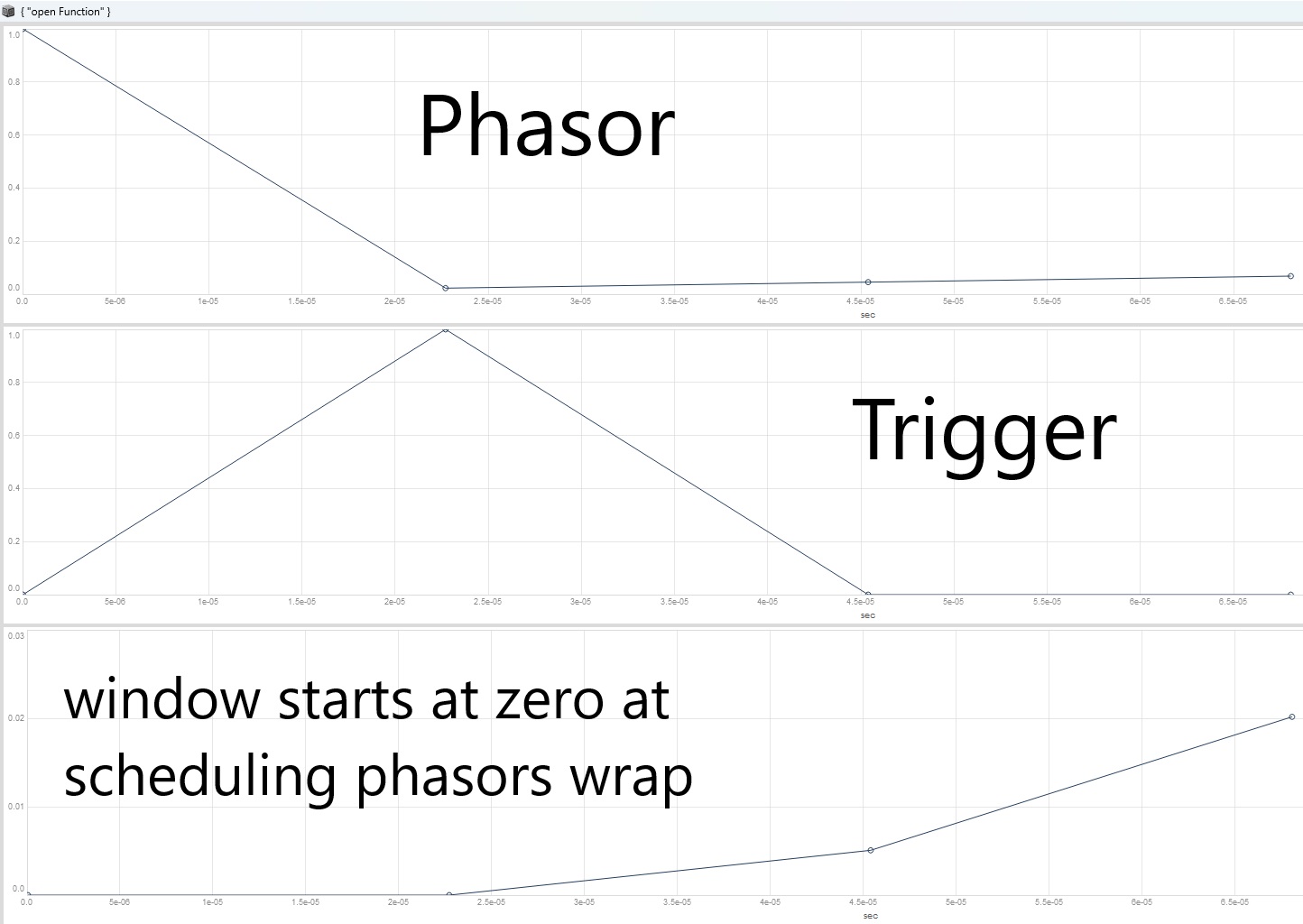
Without adding the subsample offset the window function starts from zero at the scheduling phasors wrap.

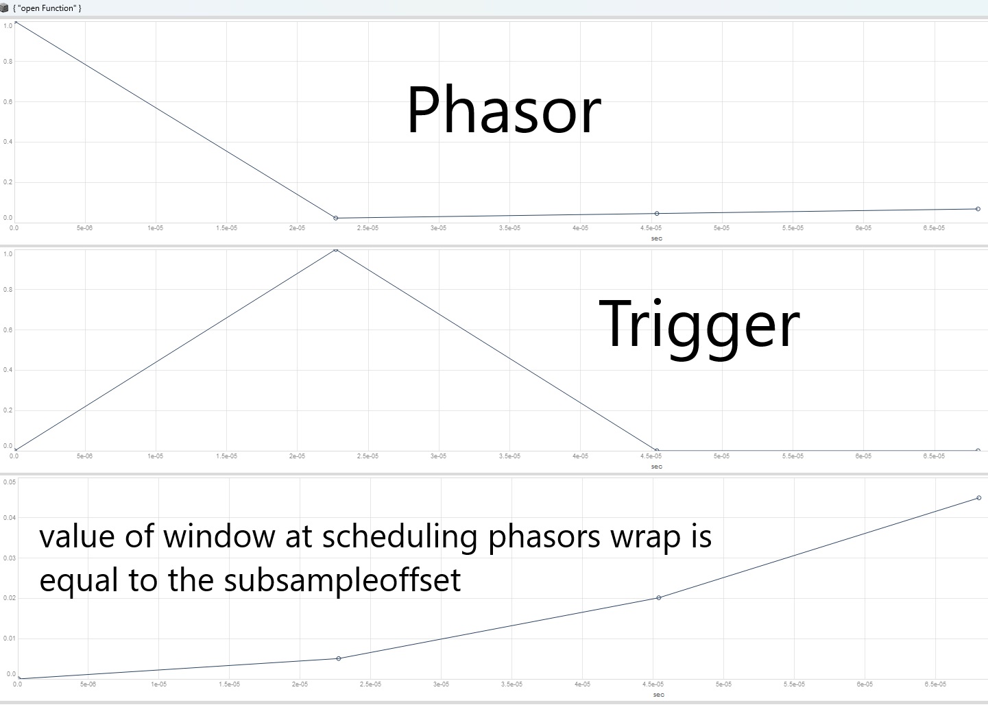
When adding the subsample offset the value of the window function at the scheduling phasors wrap is equal to the subsampleoffset

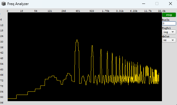
In the context of granulation, resetting the accumulator to the sub-sample offset, works perfectly to prevent aliasing for high trigger rates.

(
var rampToSlope = { |phase|
	var history = Delay1.ar(phase);
	var delta = (phase - history);
	delta.wrap(-0.5, 0.5);
};

var rampToTrig = { |phase|
	var history = Delay1.ar(phase);
	var delta = (phase - history);
	var sum = (phase + history);
	var trig = (delta / sum).abs > 0.5;
	Trig1.ar(trig, SampleDur.ir);
};

var getSubSampleOffset = { |phase, trig|
	var slope = rampToSlope.(phase);
	var sampleCount = phase - (slope < 0) / slope;
	Latch.ar(sampleCount, trig);
};

var accumulatorSubSample = { |trig, subSampleOffset|
	var accum = Duty.ar(SampleDur.ir, trig, Dseries(0, 1));
	accum + subSampleOffset;
};

{	
	var triggerFreq = \triggerFreq.kr(2000);
	var eventPhase = Phasor.ar(DC.ar(0), triggerFreq * SampleDur.ir);
	var eventSlope = rampToSlope.(eventPhase);
	var eventTrigger = rampToTrig.(eventPhase);
	
	var subSampleOffset = getSubSampleOffset.(eventPhase, eventTrigger);
	
	var accumulator = accumulatorSubSample.(eventTrigger, subSampleOffset); // <-- sub-sample accurate
	//var accumulator = accumulatorSubSample.(eventTrigger, 0); // <-- naive version
	
	var windowSlope = Latch.ar(eventSlope, eventTrigger) / max(0.001, \overlap.kr(1));
	var windowPhase = (windowSlope * accumulator).clip(0, 1);
	var window = 1 - cos(windowPhase * 2pi) / 2;
	
	var grainSlope = \grainFreq.kr(4000) * SampleDur.ir;
	var grainPhase = (grainSlope * accumulator).wrap(0, 1);
	var grain = sin(grainPhase * 2pi);
	
	var sig = grain * window;
	
	sig = LeakDC.ar(sig);
	sig!2 * 0.1;
}.play;
)
1 Like

That surely illustrates the details of the matter, thank you!! So to obtain an equally precise hard sync trigger, it needs to be able to reset the carrier and window within the grey sub sample area as opposed to a regular trigger quantized to the sampling grid, which would run counter the accuracy of the phasor ramp?

The phasor with anti-aliasing with hardsync combines the two approaches i have tried to explain above.

The carrier phasors wrap itself is placed exactly centered on the ideal phasors wrap to make the entry and exit points of the carrier phasors wrap symmetrical (anti-aliasing) and the hardsync trigger which resets the carrier phasor does not reset it to zero but to the subsample offset. When you are dealing with hardsync no window is applied.

The ideal phasors wrap would already start the new carrier or window function somewhere during the sample frame, at the moment the actual phasor wraps at the end of the sample frame the carrier or the window function should therefore already have a value which is not zero but exactly the value which is derived by calculating the subsample offset.

There are two main issues at the moment i have no idea about:

1.) The phasor with anti-aliasing does not produce similiar results to a naive phasor when driving a shaping function like simple sin. The shapers itself have to be implemented before the crossfade (LinXFade2) and have to start at 0 and end at 1. But creating basic anti-aliased ramps without shaping is even better then bandlimited Saw (watch the freqscope).

(
var phasorAntiAliased = { |freq|

	var slope, phase;
	var loopSubSample, detectTrans;
	var phaseBeforeTrans, phaseAfterTrans;
	var replacePhaseBeforeTrans, replacePhaseAfterTrans;
	var sigA, sigB;

	slope = K2A.ar(freq) * SampleDur.ir;
	phase = Phasor.ar(DC.ar(0), slope);

	loopSubSample = phase.wrap(-0.5, 0.5) + (slope * 0.5) / slope;
	detectTrans = (loopSubSample >= 0) * (loopSubSample < 1);

	phaseBeforeTrans = Select.ar(slope < 0, [
		1 - (slope * 0.5),
		slope * 0.5
	]);

	phaseAfterTrans = Select.ar(slope < 0, [
		slope * 0.5,
		1 - (slope * 0.5)
	]);

	replacePhaseBeforeTrans = Select.ar(detectTrans, [
		phase,
		phaseBeforeTrans
	]);

	replacePhaseAfterTrans = Select.ar(detectTrans, [
		phase,
		phaseAfterTrans
	]);

	// throw in your unit shapers here!!!

	//sigA = 1 - cos(replacePhaseBeforeTrans * 2pi) / 2;
	//sigB = 1 - cos(replacePhaseAfterTrans * 2pi) / 2;

	sigA = replacePhaseBeforeTrans;
	sigB = replacePhaseAfterTrans;

	LinXFade2.ar(
		sigA,
		sigB,
		loopSubSample.clip(0, 1) * 2 - 1
	);

};

{
	var sig;
	sig = phasorAntiAliased.(\freq.kr(4000));
	//sig = Saw.ar(4000); // the basic ramp is even better anti-aliased then bandlimited Saw
	sig = LeakDC.ar(sig);
	sig!2 * 0.1;
}.play
)

s.freqscope;

2.) There is no way to implement the carrier phasor with a single-sample loop in SC. In the gen~ patch the core phasor is setup with an accumulator by a combination of “+”, “wrap 0 1” and “history” which increments for every sample by a value determined by the carrier slope. Additionally you have a switch (Select) which is triggered by the sync trigger and decides if the next phase should start from zero (reset) or should continue to accumulate new values with the current slope (no reset). The reason why thats crucial is, that everytime a reset happens you need the phase before the reset (output after wrap) and the phase after the reset (output after switch) to calculate the values half a sample before and after a reset to rotate the phases accordingly. If you setup the core phase with a simple phasor you dont have access to the phase value before and after the reset trigger. Maybe there could be a hacky solution, im not familiar with.

Ok, i see!
When you mean not similar results you refer to the spike/glitch in the waveform when using sin which is caused by the crossfade (and implementing them before would warp the sine shape due to the crossfade)?
So this is not yet a tool to drive oscillators/wavetables, assuming the discontinuity is always present, just especially audible when using the sine wave and simply masked for more complex shapes?

I think the limitations of this implementation are that the shaping functions have to start at 0 and end at 1, without knowing the exact reasons why you cannot implement functions which differ from that. Its basically a saw which you can curve by inserting shaping functions before the crossfade, which start at 0 and end at 1, sin does not do that, it ends at 0.

with all these sophisticated & thought-out methods to avoid aliasing somehow it’s odd to hit such a limitation which in a way seems so simple, “just” due to the shaping. but apparently really isn’t!

yeah, thats okay. Just another reason to get familiar with other approaches and working on the export possibility from RNBO and if that doesnt work leave SC behind.

surely it’s these things that makes one keep researching and exploring other paths, which is a valuable process in itself! really hope that the RNBO will be able to solve some of these limitations, as leaving SC would means accepting limitations of other environments, which i wouldn’t be willing to do yet, rather live with these for now!
but really amazing to have these in- depth explorations nonetheless, thanks so much for the patience and dedication!

1 Like