thanks for all the replies 
defining freq and formantFreq like in the example above follows the pulsar synthesis chapter in microsound where the pulsaret length (grain duration) is always equal to 1 / formantFreq followed by silence until the next trigger arrives for the case formantFreq > freq. Both of the parameters can be modulated independently. The rectangular window in this case applied with phase < 1 should always have the length of the pulsaret. the pulsaret is always only one cycle of the waveform unless its beeing multiplied by an integer: sin((1 - phase ) ** 3 * 2pi * sineCycles.kr(4)) which concatenates a number of single cycles under the window function.
Therefore the window function in the example by @bovil43810 should be adjusted to t < 1 instead of phase < 1
(
{
var snd, snd2, freq, trig, formantFreq, t, phase, dphase;
freq = 100;
formantFreq = 400;
trig = Impulse.ar(freq);
t = Sweep.ar(trig, formantFreq);
phase = 2pi * ((1-t) * (1-t) * (1-t));
dphase = 6pi.neg * (1-t).squared;
dphase = dphase / (pi/2 + 0.065) ; // nudge
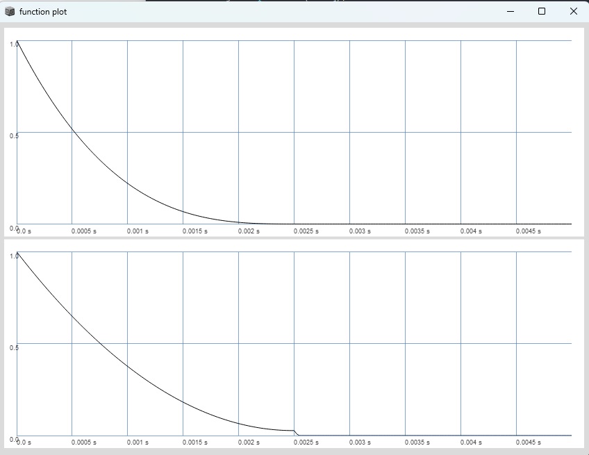
snd = SinOsc.ar(0, phase.mod(2pi));
snd = snd * (t < 1);
snd2 = SinOsc.ar(dphase * freq);
snd2 = snd2 * (t < 1);
[snd, snd2]
}.plot(0.02);
)
EDIT: im not sure if dphase should be multiplied by freq. i think it should be multiplied by formantFreq.
when you get rid of the curving thats aquivalent:
(
{
var snd, snd2, freq, trig, formantFreq, phase, sineCycles;
freq = 100;
formantFreq = 400;
sineCycles = 2;
trig = Impulse.ar(freq);
phase = Sweep.ar(trig, formantFreq);
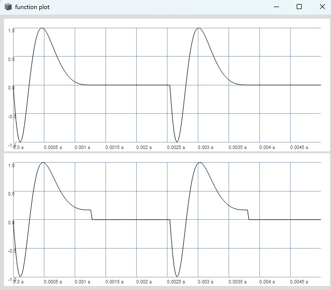
snd = SinOsc.ar(0, phase * 2pi * sineCycles);
snd = snd * (phase < 1);
snd2 = SinOsc.ar(formantFreq * sineCycles);
snd2 = snd2 * (phase < 0.99);
[snd, snd2]
}.plot(0.02);
)
thanks a lot for making the effort to adjust it for beeing used as frequency instead of phase. My algebra / DSP is unfortunately not sufficient enough to know why both of these create different results.
I havent taken SinOscs limitation of ±8p into account thanks for pointing that out @jamshark70
i now see the reason why probably using sin((1 - phase ) ** 3 * 2pi) makes more sense here, or?
Also thanks for pointing out the necessity for the phase reset.
after looking at how “total phase” is defined and the comparision of FM and PM in this thread Frequency Modulation – Phase Modulation – Delay Modulation (FM / PM / DM)
i thought freq and phase would easily be interchangeable. Seems to be more complicated then i thought, sorry for the noise.
As always, some concepts i try to merge (in this case the chirp beeing used for Pulsar Synthesis + the possibility for aliasing free high index FM on Sin/Saw/Square which needs Squine) are simply not possible or easily not possible.
My specific pulsar implementation was taken from / inspired by @nathan wonderful blog post Pulsar Synthesis | Nathan Ho